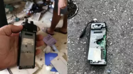
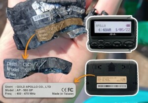
In the last few days, we’ve seen news reports of pagers and walkie-talkies owned by Hezbollah exploding in Lebanon. Here’s how we think this operation was carried out.
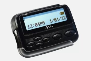
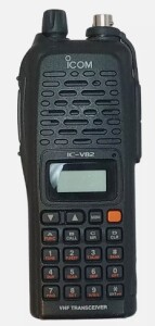
The devices in question appear to be the Apollo AP-900 pager, and the ICOM IC-V82 transceiver. These models appear to be out of production, but they are still readily available. In fact, the links above are to them on eBay.
The Pagers
The first round of simultaneous explosions involved the pagers. When I first heard about it, I wondered whether it was some kind of software hack, which conceivably could cause an internal Lithium-Ion battery to explode. But it turns out that’s impossible, because the pager actually uses an alkaline AAA battery. (Since Lebanon’s power grid has collapsed, it makes sense to use alkaline batteries, rather than worrying about how to recharge the batteries.) Even if you caused a direct short in a AAA alkaline, not much would happen. Therefore, the pagers certainly had some type of explosive installed in them at “the factory.”
Hezbollah (wisely) abandoned use of things like cellular phones for communications with their people in the field. Since a cell phone relies upon transmitting a signal, even to receive, there’s always a possibility of it being monitored or tracked. Even receiving information via the Internet means that you leave a trace by connecting to some other computer. If your adversary is Mossad, it’s almost certain that they’ll eventually start tracking it or monitoring it. So it’s much smarter to use passive receivers to get your instructions.
This is a time-honored tradition. For example, the words “blessent mon cœur d’une langueur monotone” were famously transmitted by London radio to inform the French resistance that the D-Day invasion was about to begin. (The movie Red Dawn uses the phrase “John has a long moustache.” This is actually a translation of “Jean a de longues moustache,” another coded message (or dummy message) from the movie The Longest Day. I’ve still never figured out whether that phrase was really used on D-Day, or whether it was from the movie.)
And to this day, numbers stations transmit coded messages to be picked up by agents in the field. The general idea is the same: The agent needs nothing more than a passive receiver to get the message. They don’t have to transmit or make their presence known in any way. While the existence of the message (or, if the code is broken, the contents of the message) is known to the other side. But there’s no way of knowing who received the message.
The exploding pagers were just passive receivers. While that model seems to be out of production, you can buy similar ones new on Amazon. They are typically used, for example, in restaurants to let you know your table is ready. They can also be used in a hospital or factory to send messages to employees on the premises. The transmitter is kept locally. When a customer’s table is ready, or a nurse is needed, you simply push the right button on the transmitter, and the pager will sound off.
But there’s no way of knowing who has a pager. Unless you see or hear someone using it (or perhaps, if you are extremely close to them picking up spurious emissions), there’s no way of knowing who has one, or who got the message. You can receive messages anonymously.
Making it Explode
But if you get your hands on the passive receiver before the end user does, there is something you can do. You can make it blow up! All you need to do is add some explosive material, and a means of detonating it remotely. Installing that requires a bit of stealth. But once it’s in place, it’s easy to detonate.
The pager, whenever it’s turned on, listens to its frequency of about 450 MHz, listening for incoming messages. When a message is received, the internal circuitry turns it on and displays an alphanumeric message. It would be relatively easy to tap into this circuit. So, for example, when the incoming message is 011001011011001, instead of displaying it alphanumerically, it just sends a message to the explosives that it’s time to detonate.
If you are on the other side, it’s not particularly difficult to figure out what frequency the pager is listening for. If you capture one enemy pager, then you’ll know that information. Or if you just listen long enough, you’ll realize that there’s a new pager transmitter on the air. All you need to do is transmit on that frequency and send the detonate code. If you’re not sure, or if the pagers are using multiple frequencies, you simply repeat the message. You already know the detonate code, because you’re the one who put it there.
The Walkie-Talkies
Update: Icom Japan has issued a statement pointing out that this model has not been manufactured for ten years. It seems likely that the radios in question were counterfeit, even before the addition of the explosive.
The ICOM VHF transceivers are a slightly different issue, but it’s a quite easy matter to come up with the electronics to detonate one. The IC-V82 is a fairly popular amateur 2 meter transceiver, as shown by these reviews. The version sold to Amateurs in the U.S. cover 144-148 MHz, but other versions probably cover approximately 144-175 MHz.
The radio can be tuned to multiple frequencies, and your intelligence needs to figure out which one. Again, if you are unable to capture one, it’s an easy enough matter to simply listen and figure out what frequencies the enemy is using. When the time comes, you can transmit on all of them, and most radios will be tuned to one of those frequencies. If they hear the right tone or code, they will detonate.
This radio probably does have a Lithium-Ion battery. It’s not involved in the initial explosion, but once the small bomb inside goes off, the battery probably adds considerably to the destruction.
Even though this radio is also capable of transmitting, you are relying only upon the receiver in order to blow it up. You send a signal on whatever frequency the receiver is tuned to. That signal activates the detonator you installed. That circuit can be simplicity itself.
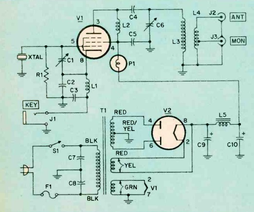
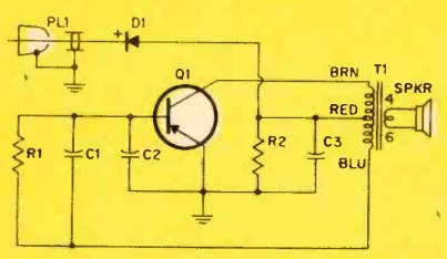
About 40 years ago, I built a circuit that could be used in that application. It never really caught on, but for a time, U.S. Amateur Radio operators were toying with the idea of a “long tone zero” protocol. If you needed help in an emergency, you could transmit a zero on your Touchtone pad, hold it down for a few seconds, and that tone would be used to turn on a receiver at someone’s house. It was a good idea, but it never caught on. But I built a decoder and hooked it to a receiver that I left on 24/7. If someone needed to waken me, all they had to do would be to hold down their zero button for a few seconds, and my radio would come to life, full blast.
In my case, that circuit was on a PC board measuring a few inches. But such a device could easily be constructed to be microscopic, and inserted into another component. It’s hooked up somewhere in the radio’s normal audio stages. When the correct tone is received, the circuit, instead of turning on the speaker, would detonate the explosive.
Sending the Detonate Signal
Once the Israelis know the frequencies, it’s an easy matter to transmit a signal to all affected devices. The distance from Tel Aviv to Beirut is only 208 km (130 miles). The distance from the Israel border to Beirut is even less. So it’s a fairly trivial matter to transmit a signal from an airplane on the walkie-talkie’s frequency (about 150 MHz) or the pager’s frequency (about 450 MHz). According to this line-of-sight calculator, an airplane at an elevation of 10,000 meters (30,000 feet) has a line of sight of 357 km. In other words, a VHF or UHF signal transmitted from such an airplane over Israel will be heard loud and clear in Beirut, or almost anyplace in Lebanon.
Getting the bombs inside these devices was quite a coup by Israeli intelligence. But they would be quite easy to disguise. The circuit could be small enough to squeeze inside a replica of a capacitor or resistor that was already there. But once it’s in place, the task of actually detonating it is trivially simple.
Some links on this site are affiliate links, meaning that this site earns a small commission if you make a purchase after using the link.
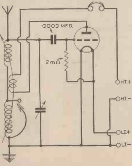
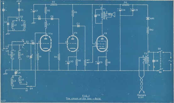
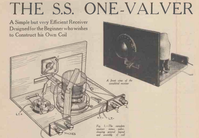 When the September 1939 issue of Practical Mechanics was on the newsstands, Britain was already at war. But if someone needed a radio, this simple design was perfect for wartime austerity. The only manufactured components needed were the tube, one variable capacitor, one fixed capacitor, one resistor, and the headphones.
