 This young woman undoubtedly took home the blue ribbon in the 1960 science fair. And she certainly earned herself considerable street cred as a mad scientist by putting together this Jacob’s ladder, by carefully following the plans in the November 1960 issue of Electronics Illustrated.
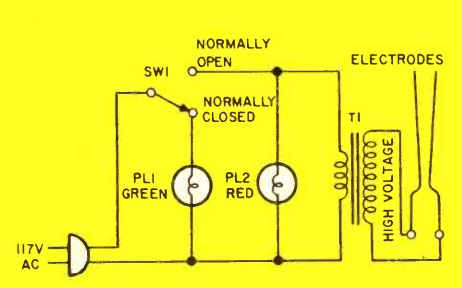
As revealed by the schematic diagram below, the circuit is simplicity itself. It simply takes normal household current and runs it into a transformer which steps it up to 12,000 volts, which is fed into two electrodes. One way or another, there is going to be an arc between the two conductors. It will follow the path of least resistance, and thus starts out at the bottom, where the two metal rods are closest together.
The arc heats the air right above it, which ionizes the air. The ionized air thus becomes the new path of least resistance, and the arc moves upward. The process repeats until it reaches the top, at which point a new arc forms at the bottom.
The critical component, of course, is the high voltage transformer. In 1960, it was available in the form of a neon light transformer, for $12 plus shipping. Of course, neon signs still exist, and you can buy the transformers on Amazon. This modern replacement is rated at “only” 10,000 volts, but it seems like that should be sufficient.
The 1960 article includes a number of important safety features. First of all, the electrodes are safely behind a sheet of 1/32″ clear acetate. This also appears to be available on Amazon.
And the choice of switch ensures that the device isn’t turned on accidentally. The power switch is a momentary switch, meaning that when you let go of the switch, it turns off. It’s a SPDT switch, meaning that when it’s off, another contact is energized. This is wired to a green pilot light that indicates that the device is plugged in. The switch has a safety cover, meaning that one needs to consciously lift the cover to flip the switch.
The article begins by saying that “if the directions given in this article are followed to the letter, there is no danger of shock. Don’t take short-cuts or omit the built-in safety features of this model; it is poor economy to leave out relatively inexpensive components that might prevent a nasty shock.”
These days, when one reads safety warnings, there’s a tendency to ignore them. But in 1960, when a warning like this was included, it’s because the activity in question was, indeed, dangerous, and you really needed to be careful. So I believe this project is suitable for mature students, working under the supervision of a competent adult. But this contraption is potentially lethal, and great care must be taken in its construction and use. In 2016, a Michigan teen was killed trying to build one, and we don’t want any of our readers to suffer the same fate. So please be careful.

