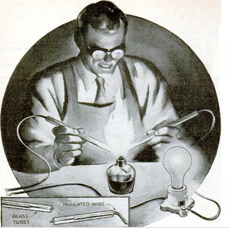
 The young man shown on the cover of the September-October 1968 issue of Elementary Electronics, along with his loyal beagle, are taking a break from baseball to pull in some DX on their Heathkit GR-43 portable shortwave receiver.
But the portable was pulling in DX from all corners of the world, since it had been effectively souped up, thanks to the “DX Devil” described in the magazine.
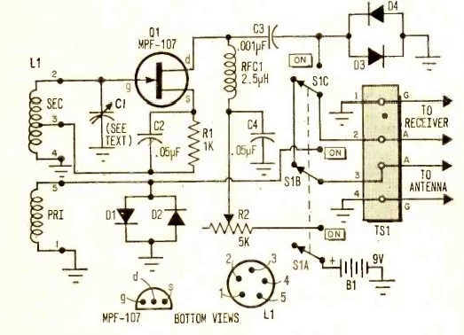
The DX Devil was a one-transistor (MPF-107 FET) regenerative preamplifier, which gave 40 dB gain from 3-30 MHz. In addition, it eliminated images, since the tuning was sharp enough to eliminate the offending signal 910 kHz away. And since it was regenerative, it also served as a Q-multiplier to vastly increase the set’s selectivity. The author noted that most shortwave sets selling for less than $75 lacked a tuned RF stage, and that the addition of the DX Devil would vastly increase both sensitivity and selectivity.
Three plug-in coils allowed for band selection. The article noted that the unit’s performance would be especially noticeable on higher frequencies. Tuning was accomplished with a vernier dial to allow amplification of a very narrow bandwidth. In operation, the regeneration control was set to just below the point of oscillation, ensuring maximum gain.
The author noted that the performance of the DX Devil would be inversely proportional to the quality of the receiver used: “The worse your set is, the more startling will be the results.” He reported that on a pre-WW2 receiver, 28 MHz signals were lifted from inaudibility to 100% copy. But even on a modern dual-conversion superhet, he reported much more readable signals, with the S-meter jumping 20-30 dB.
Operation of the unit would require two hands. First, you would tune the receiver to the desired frequency. Then, you would rock the tuning control back and forth while slowly increasing the regeneration. I imagine that it would take a bit of practice, but eventually, you would find that the signal strength had jumped considerably.
Despite being concealed in the cover photo, the DX Devil did require a direct connection between an external antenna and the antenna terminals of the receiver. The four diodes shown in the circuit were to provide protection in case the DX Devil was used in close proximity to a transmitter, or in case of static discharges. At the low signal levels, they would have little effect on the circuit, but when presented with a stronger signal, they would provide a low-impedance path to ground.
The designer of this circuit is a familiar name to readers. The circuit was designed by the author of the article, Hartland B. Smith, W8VVD, currently licensed as W8QX. He was first licensed in 1941, and was the author of many construction articles, such as one for a steam-powered transmitter previously featured here. He was also the creator of the HART-65 transmitter. A link to some of his websites can be found at the steam-powered transmitter post. Tomorrow, we’ll bring you an even more interesting article by the same author from 1958.
Most times when I post an illustration such as this of a completed project in use, I need to take a certain amount of poetic license to name the characters. So ordinarily, I would probably assign the name “Junior” to the young SWL, and “Fido” to his canine companion. But in this case, such artistic license is not necessary, since the magazine gives the full name of the SWL, namely, one Gary Bulger. And the dog’s name is Gladys.
I wasn’t able to track down Mr. Bulger, who I’m guessing lived in the New York area in 1968, since that’s where the magazine was based. But people Google their names from time to time, and if you are the young Mr. Bulger shown in the photo, we would love to follow up with your recollections of this photo. Please comment below or e-mail me at clem.law@usa.net.