Amateur station licenses weren’t being issued during the war, but the FCC continued to conduct exams and issue operator licenses. And there was a big demand for operators, both in the military and commercially, so learning Morse Code would be an important skill in 1943, and the January and March, 1943, issues of Popular Mechanics carried companion projects to assist a student in learning the code. The January issue carried plans for a simple code practice oscillator using a 25A7GT tube which ran on 120 volt house current. The set was billed as a “safety code oscillator,” the safety feature being that both the filament and B+ were dropped down to 25 volts by use of a “curain burner” resistance line cord.
The writer, W9SFW, seems to have realized, however, that the setup wasn’t totally safe. Depending on how the plug was inserted, there was a 50/50 chance that the exposed “ground” connections on the exposed chassis were actually hooked directly to 120 volts. The solution was to plug it in the other way. In the case of the code oscillator, this would be apparent, since the oscillator would make noise even with the key up.
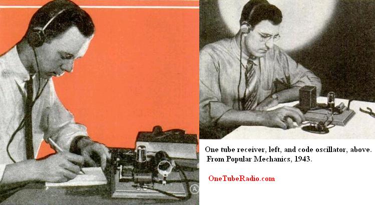
The March issue carried a simple one-tube regenerative receiver, using the same tube and many of the same parts. Since listening to actual code on the air was the best way to learn, this set would allow the builder to tune about 6-11 MHz, frequencies that would have been packed with CW signals during the war. The author notes that “once some code efficiency is obtained, listening-in on actual code signals is the best way to increase your code receiving speed and learn real message-handling procedure that will be of help in service training.
Since unlike the oscillator, the receiver would operate just fine even with the chassis “hot,” the article advises that the polarity of the cord should be tested and then marked. To test it, a light socket was hooked to one of the ground points, with the other side to an actual ground. If the bulb lit up, then the plug was the wrong way and should be reversed. With the correct polarity and the “curtain burner” cord dropping the voltage, the set would be relatively safe.
It should be noted that there’s really no safe way to build this set on an exposed breadboard without the “curtain burner” cord. Even though polarized cords are available, which are a step in the right direction, there’s another problem. One could use a sufficiently large 330 ohm resistor to drop the voltage, but one end of that resistor would still have 120 volts on it. If you do overcome that safety obstacle (by not leaving connections exposed), all of the parts required for this simple set should be readily obtainable. The set uses two variable capacitors, one for tuning and the other for regeneration. As discussed in the article, the exact values are not critical. The coil is wound on a cardboard form. The fixed capacitors are readily available, with the added bonus of the modern equivalents being much smaller than the 1943 versions.
The tube is a dual tube, and in both circuits, half the tube is used as the rectifier.
Click Here For Today’s Ripley’s Believe It Or Not Cartoon
