2018 Update: This page was written in 2015, after the FCC reduced the fee for the GMRS license. GMRS remains a good option for many emergency communications applications.
You can obtain a GMRS license by mail or online. As with many bureaucratic activities, it’s somewhat more complicated than necessary, but not particularly difficult. The fee for the ten year license is currently $70. Just follow these steps:
Applying for the License Online:
You can read the full instructions at this page on the FCC website. It’s basically a two-step process. First, you will need to set up an account on the FCC Universal Licensing System (ULS). When you do, you will receive an “FRN” (FCC Registration Number) and password. If you have future business with the FCC, you’ll use this same account. You will sign up at this page on the FCC website.
After you have the ULS Account set up, you will go to this page on the FCC website to start the application. All of the questions on the application should be self-explanatory.
Applying for the License By Mail:
To apply by mail, you will actually need to send three separate forms from the FCC website:
Download form 605 first, since it contains most of the general instructions. For more information, the full instructions can be found on page 9 of this FCC document.
On May 20, 2015, the FCC announced that it reduced the license fee for GMRS radio licenses.
This change has a significant implication for those looking for an inexpensive method of family communication, especially for emergency preparedness. The change allows hams and others to potentially provide an important service to their neighbors, at a very low cost. To see how it’s important, we need to look at the history of GMRS radio, and the related FRS radio service.
FRS Radio

Inexpensive FRS radios.
 In 1996, the FCC created the Family Radio Service (FRS), which allowed unlicensed use of UHF radios on 14 channels. millions of such radios
 were sold, and even the most inexpensive versions (often under ten dollars) provide quite reliable communications over short distances (less than a mile).
The FCC imposed a number of technical requirements for these radios. First of all, the maximum power allowed was 500 milliwatts (1/2 watt). In most cases, this low power is not a significant limitation. The most important limitation, however, was that the antenna had to be permanently mounted to the radio, with no method of connecting an external antenna.
This is a very significant limitation because on the UHF frequencies used by these radios, the main factor in determining distance is the height of the antenna. This is because UHF radio waves behave almost the same as light waves: they travel in a line of sight. Radio waves have some ability to penetrate obstructions, but this is very limited. Therefore, an FRS radio really has about the same range as a flashlight. If you can’t see the other radio, then you probably won’t be able to communicate with it. (Again, the radio waves can penetrate some obstructions, but this ability is very limited.)
If you have a flashlight in your hand, then you can’t be seen very far away, because the light beam will hit obstructions. And an FRS radio works under the same principle: Your signal won’t get out very far because it will hit obstructions. On the other hand, if you climbed a mountain with the flashlight, then it could be seen for many miles, because you would be up clear of the obstructions. And an FRS radio would work the same way. If you were on top of a mountain, then you would be able to communicate many miles, as long as the person at the other end was able to see the mountain off in the distance.
It’s usually not practical to climb a mountain to extend the range of your radio. However, it’s not the location of the radio that is important. The critical factor is the location of the antenna. There’s a reason why radio and TV stations spend money building expensive towers, and that reason is to increase the height of their antenna.
But this is not possible with FRS radios, because they are not allowed to have external antennas or any way to connect an external antenna. Therefore, their range was extremely limited.
One manufacturer cleverly exploited a loophole to market an FRS radio with the functional equivalent of an external antenna. Radio Shack sold an FRS radio with an external microphone. The radio itself was sealed inside a unit that mounted to the top of a vehicle with a strong magnet. The antenna was permanently attached to the radio, so it met the FCC rules. But all of the controls were mounted on the microphone, which could be used inside the car. Having the antenna (and radio) on top of the car significantly extended the range of the unit.
GMRS
The General Mobile Radio Service (GMRS) dates back to the 1960’s. Initially, the equipment was very expensive, but it provided a very versatile method of communications. The rules allowed up to 50 watts, and external antennas were the norm. GMRS could provide reliable communication over many miles. Depending on local conditions (in particular, antenna height), a range of 20-50 miles would be quite common. But the equipment was rather expensive, and GMRS was never adopted to its full potential. Fifteen channels are assigned to GMRS. A license is required, and the license carried a fee. Given the versatility of GMRS, this was actually quite a bargain, especially considering that the equipment would cost hundreds of dollars.
When FRS radio was created in 1996, the situation soon changed. Seven of the fourteen FRS channels were shared with GMRS. In other words, an FRS user could talk to GMRS radios on channels 1-7. But there were relatively few GMRS users, and this option was rarely utilized. While they were compatible, the two services served different needs. GMRS used expensive equipment to communicate over fairly long distances. Most of the millions of FRS radios that were sold were used for very short-range communication, or even as children’s toys. While having the shared channels was probably a good idea, I don’t think the FCC anticipated how popular FRS radio would become, or how inexpensive the radios would be. The net effect was that the seven shared channels became cluttered with FRS users, and were generally avoided by GMRS users.
Some manufacturers, however, started marketing around the new possibilities. They started selling 15-channel portable GMRS radios, and the prices kept coming down. These units had the best of both worlds: They could use higher power than the FRS radios, but they could still communicate with the cheaper radios on 7 channels. And most importantly, they had provision for an external antenna. Therefore, they had the greater potential range of a GMRS radio.
When prices of such radios got less expensive, many users (probably most) started ignoring the licensing requirement. This is understandable, since from their point of view, they had in their hands a slightly better FRS radio, which probably cost less than $90. It made little sense to pay an additional $90 for a license, especially if they used only channels 1-7. While a license was technically required on these channels, it would be essentially impossible to tell whether the user was using a license-free FRS radio or a GMRS radio for which a license was required.
Meanwhile, the price of these radios kept getting lower and lower, and manufacturers had to come up with a marketing angle. They started by printing on the package the range of the radio in miles. Remember, the range of the radio is limited by the location of the antenna. If you are standing in a valley, the range will probably be less than a mile. If you’re standing on top of Mount McKinley, then the range will be hundreds of miles. And in general, the quality of the radio has very little to do with it. So the manufacturers started inflating the range estimates for their radios. These claims were not false–they were merely misleading. After all, if you climbed Mount McKinley with the radio, you would easily get the advertised range.
So one manufacturer would be selling a radio with a “one mile” range, which would probably be a reasonable estimate in normal use. But another manufacturer could take a nearly identical radio to a small hill and truthfully state that it had a two-mile range. Another manufacturer could take his identical radio to a slightly larger hill and truthfully claim a range of three miles. The products didn’t need to improve–the manufacturer just needed to find a bigger hill.
Chances are, the “30 mile” radio wasn’t any better than the “2 mile” radio right next to it on the shelf. But understandably, consumers were more likely to buy the “30 mile” radio.
Soon, distance claims were strained to the point of incredulity, and the marketing people needed to come up with a different angle. Some manufacturers were selling 14-channel FRS radios. Some manufacturers were selling 15-channel GMRS radios. There were really only two differences. First of all, the 15-channel GMRS radios required a license, but this requirement was routinely ignored. The only real advantage that the 15-channel GMRS radios had was that they could be used with an external antenna, the one thing that would really increase their range. But most people used these radios only as portable walkie-talkies, and most people didn’t realize that they could get significant range by use of an outdoor antenna. So the ability to use an external antenna was never a selling point.
At some point, some manufacturer realized that they could distinguish their product by selling a 22-channel radio. The radio would be a combined FRS-GMRS radio that could use the 7 shared GMRS-FRS channels, the 7 FRS-only channels, and the 8 GMRS-only channels. This was legal, as long as the radio met the requirements for both services. They had to use the lower power on the FRS-only channels. (And I suspect that most of them simply used the lower power on all channels.) But more importantly, the combined unit had to have a permanent antenna, with no possibility of hooking up an outside antenna. In other words, the marketing angle of “more channels” had the result of taking away the one advantage of GMRS: The ability to use an external antenna.
Very few consumers appreciated the advantage of an external antenna, and most of the “inferior” 15-channel radios soon departed the market in favor of the “improved” 22-channel models. On the shelf, the competing products were distinguished mostly by the meaningless “mileage” claims on the package. Understandably, most purchasers didn’t bother to get the $90 license for their $20 radio. The license wasn’t even required for channels 8-14, and they could be used with virtually impunity on channels 1-7, even though a license might technically be required there. There was no real advantage in using channels 15-22 where the license was required.
Millions of these radios were sold, and most of them were probably put away when the owners realized that the mileage claim on the package was meaningless.
Family Communications Tool
I’ve never bothered getting a GMRS license, mostly because of the $90 fee. While it would occasionally be nice to have, it’s really not worth it. As an amateur radio operator, I can get the same results with amateur radio. But occasionally, having a GMRS capability would be helpful. For example, a GMRS radio would make it possible to communicate with the kids within a mile or so.
In general, it’s not necessary to have both antennas at a high location. Remember, an FRS radio is like a flashlight. It can’t be seen very far away by someone else standing on the ground. But it can be seen if the other person is at a high location. Therefore, to turn it into a reliable method of family communication, it’s only necessary to have one good antenna at home, or on a vehicle. The other person can be using an inexpensive FRS radio with a built-in antenna, but there will still be acceptable range.
Potential for Emergency Communications
 And in an emergency, it would be possible to communicate with neighbors with an FRS radio. Several years ago, someone proposed a “National SOS Radio Network” to educate owners of FRS radios as to their possibilities for emergency communications, but the group’s website is now defunct and there appears to be no more effort to publicize the idea. It was a very good idea, although very limited in scope: After a disaster which wiped out other forms of communications, people would have the capability to talk to their neighbors, as long as they knew other people would be listening on the same emergency channel.
The DC Emergency Radio Network was a similar plan, but it also appears to be defunct.
Again, it’s not necessary for both sides of the transmission to have a good antenna. But if one person in the neighborhood has a good antenna, then the other neighbors will be able to communicate with that person in an emergency, even with “toy” radios. And if that person is capable of worldwide communication without commercial power (as I am), then the whole neighborhood is suddenly linked to the outside world.
It should be noted that an FRS radio would be a poor first choice for summoning help in an emergency. It’s unlikely that anyone would be monitoring at any given time, and when I get my GMRS license, I have no plans to continuously monitor for potential emergencies.
But after a widespread emergency, such as a blizzard or earthquake, normal telephone service or even cell phone service might be unavailable. After such an emergency, neighbors might have a need to communicate. This wouldn’t necessarily be to summon assistance. It might just be a matter of wanting to check on other neighbors.
If one neighbor has a GMRS station and can plan to monitor after other communications facilities are unavailable, this would provide a link to nearby neighbors with nothing more than a “toy” FRS radio. If they know to turn it on in case of an emergency, and to what channel, then it seems to me that this could fill an important need after a disaster.
Getting a GMRS License and a Radio
Since I wanted to avoid the $90 fee, I’ve considered mounting an FRS radio in a weatherproof container outside, with the microphone, speaker, and power supply mounted inside. This could be used legally without the $90 license, and would function about as well as a licensed GMRS station.
With the fee reduced, it’s now more reasible to simply get a GMRS radio and the license.
Unfortunately, the very common and inexpensive 22-channel radios are useless for my intended purpose, since they don’t allow an external antenna. Fortunately, there are a few of the 15-channel radios available, and they do allow an external antenna connection.
One possibility, of course, is one of the many cheap Chinese handheld radios that are available. For example, my Baofeng UV-5R is capable of transmitting on the GMRS frequencies. Unfortunately, however, this is not a legal option. GMRS equipment needs to be specifically certified for GMRS use, and this radio is not. (In addition, the wideband receiver of the Baofeng desenses quite badly with an external antenna, and probably wouldn’t perform very well on receive.)
One of the Wouxun Chinese handheld radios appears to have received FCC certification for GMRS use, but I’ve been unable to find this model for sale.
One possibility would be a professional-grade transceiver such as the Icom IC-F21 GM, but that would entail more expense than I wanted. Cobra also makes a combination GMRS-Marine radio . This is somewhat out of my price range, but it could be a good choice for someone looking for a marine radio.
Fortunately, there are apparently a few manufacturers who didn’t get the memo about the marketing advantages of 22 channels, so there are a handful of the 15-channel GMRS transceivers available. At one time, the best bet was the Audiovox GMRS1535 . This is a consumer-grade “blister pack” radio and sold at “blister pack” prices.
According to a couple of reports, the antenna appears to be removable with an SMA connector . If this is the case, then this radio can be used with an external antenna. However, many of these radios do not have a detachable antenna. The one I ordered had a permanent antenna. Therefore, it appears that Audiovox made two versions of the same model. Unless you can look at the radio you are buying, you can’t assume that the Audiovox has the option for an external antenna.

 Currently, the best available option for a GMRS radio with external antenna appears to be the Midland MXT105. This is a 5-watt radio. It includes an external magnetic mount antenna with a cable of about 20 feet. For most users, this antenna could be mounted on a metallic surface and give good results. For better results, a more permanent antenna can be used.
This radio runs off 12 volts. For many emergency applications, powering it with a battery would be the best option. Another alternative would be a power supply such as this one.
This radio will be able to communicate with FRS radios. Since it has an external antenna, you should get good results, even in connection with inexpensive FRS radios. You can buy the MXT105 at Amazon or WalMart. Many WalMart stores will have the radio in stock, but to make sure, you can order online at this link, and then pick the radio up at the store the same day.
Another possibility is the Blackbird RR5000 , a 15-channel GMRS transceiver that appears to have provision for an external antenna.
Most of my readers have the technical wherewithal to set up a GMRS radio, and you should consider taking this step in order to serve your community in case of emergency. If you’re a ham, you’ll probably recall that the Amateur’s Code says that your “station and skills are always ready for service to country and community.” It seems to me that with a very small investment, you could be prepared to do just that.
For more information on the basics of emergency communications, please visit my emergency communications page, which is also available as a Kindle book .
.
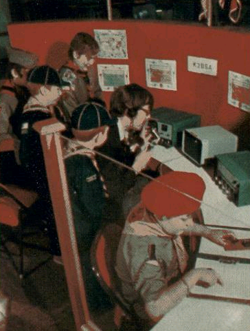 Shown here is the flagship Amateur Radio station of the Boy Scouts of America, K2BSA, as it appeared 40 years ago this month, in the August 1975 issue of Boys’ Life.