Category Archives: Radio

Radio and the Longitude Problem

RadioLongitude

The wireless telegraph  solved the Longitude Problem once and for all.    Many maritime disasters over the centuries were the result of sailors not knowing their longitude. Determining latitude is relatively simple. From any position on earth, it is easy to determine the local time by observing the sun or stars. When the sun is at its highest point for the day, this is, by definition, noon local time. The sun’s altiude at that time can be used to quickly determine the observer’s latitude.

Longitude, however, was a much more difficult problem. With instantaneous communication, it’s trivially simple to determine longitude. The observer merely determines local noon, and then compares that with the local time at a known longitude. The difference in time can quickly be converted to difference in longitude. If it is noon at my location, and I know that it is 6:00 PM at Greenwich, then I instantly know that I am 90 degrees west of Greenwich. The time diference is 6/24 of one day, which is 1/4. Therefore, the difference in longitude is 1/4 of 360 degrees, or 90 degrees.

Of course, instantaneous communication was not availalbe for most of the history of navigation. Therefore, the problem remained formidable. It wasn’t until the late 1700’s that sufficiently accurate chronomoters became available. And even then, a backup method (careful observation of the eclipses of known stars by the moon) involving laborious calculations was required.

These problems were  solved by the use of wireless time signals. A mariner could set his chronometer accurately (generally, to about a tenth of a second) by use of time signals broadcast by stations such as NAA in the United States or the Eiffel Tower in France.

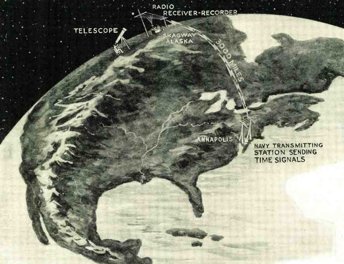
But even as recently as 90 years ago, this problem was still receiving attention, as shown by the article in the November, 1924, issue of Radio News. Listening to the time signal by ear and noting the time on the chronometer was accurate enough for maritime navigation. But for land surveying, a more precise automated method was necessary. Telegraph lines could be used, but the relays used in long lines introduced a delay. Radio was ideal, since the only delay was the speed of light, and even that could be accounted for. The article explains how the time radio time signal from the naval observatory was graphed along with the time from a locally calibrated chronometer. The result was a very accurate indication of the time difference, and thus the longitude difference, between the two locations.

The article shows how the time signal from Annapolis, Maryland, was used to determine exact longitude in Skagway, Alaska, 3000 miles away.

Read More at Amazon


Combination Book Light-Radio, 1939

BookLightRadioI’m not sure exactly why one would want a combination book light and radio, but if you wanted one 75 years ago, Popular Science for November 1939 showed you how to build it.  It was billed as being extremely useful for reading in bed, assuming of course, that you have a handy aerial and ground connection nearby.

The radio itself is a basic one-tube BookLightRadioSchematicregenerative receiver.  It uses two trimmer condensers, one of which handles tuning and the other regeneration.  The particular tube used in this circuit appears to be unobtanium.  It looks like a standard miniature tube, but it’s actually a Hytron “Bantam Junior,” with a proprietary bakelite base.  The receiver drove a pair of headphones, presumably for quiet bedtime listening while reading.


1934 One Tube Radio

Nov34QST

Occasionally here at OneTubeRadio.com, we have, well, a one tube radio. This one appeared 80 years ago this month in the November 1934 issue of QST.

This circuit uses half of the dual-triode Type 19 tube as the regenerative detector, and the other half as an audio amplifier. It’s not very different from the 1950 Boys’ Life receiver I featured in an earlier post.  The tube is equivalent to the slightly more modern 1J6 with an octal base, and that tube is available for less than $4 from Antique Electronic Supply.

If you’re looking for a simple circuit for a one tube radio, here it is! For pointers on finding some of the other parts, see my earlier article on the subject.


WCFL vs. Border Blaster XEAW


MilwJournal103039The radio column for the Milwaukee Journal 75 years ago today, October 30, 1939, touches on the phenomenon of “border blasters” in Mexico and how they affected U.S. radio listening. Milwaukee was essentially the same radio market as Chicago. Even though Milwaukee had its own stations, listeners there ordinarily listened to the Chicago stations, including WCFL, then on 970 kilocycles. In 1939, WCFL carried the NBC “Blue” network, and would have been the main outlet in Milwaukee for listening to that network.

During the daytime, WCFL would have provided good coverage to the Milwaukee area, but the situation was different at night. The radio columnist, Edgar A. Thompson, pointed out that listeners who wanted to hear the NBC symphony, conducted by Arturo Toscanini, especially in the northern suburbs of Milwaukee, would experience difficulty to to the 100,000 watt signal of Mexican station XEAW in Reynosa on 960 kilocycles.

The solution was to tune instead to KDKA Pittsburg on 980 kilocycles, where the columnist reported that he heard the entire concert on a five tube “midget” table radio with good reception.

XEAW was one of the “border blaster” stations in Mexico, broadcasting with powerful transmitters that blanketed North America from just across the Mexican border.  XEAW was owned for most of the 1930’s by Dr. John R. Brinkley, a Kansas physician (with a degree from a diploma mill known as the Eclectic Medical University in Kansas City).  Brinkley’s most famous cure involved an extract from goat testicles that would allegedly cure various maladies.  By 1939, Brinkley had sold the station to Carr Collins, another practitioner of alternative medicine, whose “Crazy Crystals” from Mineral Wells, Texas, were reported to have various curative properties.  It was probably Collins who was causing the interference to WCFL reported in this news item.

Brinkley owned at one time or another various of the “Border Blaster” stations in Northern Mexico, and he was quite well known throughout the United States.  My dad recounted hearing Dr. Brinkley, and his broadcasts were apparently a source of amusement on the farm radio in Indiana.  XEAW, weighing in at only 100,000 watts was one of the lower powered border blasters.  Some operated with power of up to 500,000 watts.  At one time, Brinkley was the owner of the most powerful radio station in the world,

The problems caused by the “Border Blasters” were largely solved in 1941 by the North American Radio Broadcasting Agreement.  Unlike Canada and the United States, Mexico had never been assigned any “clear channel” stations, and it therefore had little incentive to rein in powerful stations like XEAW.  The new agreement assigned clear channels to Mexico, on 800, 900, 1050, 1220, 1550, and 1570 kilocycles.  To make room for the new channels, the broadcast band was extended upward from 1500 to 1600 kilocycles.  As a result, most American stations changed frequencies (usually moving up the dial) the morning of March 29, 1941.  At that point, WCFL moved from 970 to 1000 on the dial.  It remained there as WCFL until 1987, when it became WLUP and later WMVP, which still inhabits 1000 on the dial.

Presumably, after 1941, WCFL’s listeners north of Milwaukee no longer had to worry about goat testicles interfering with their concert listening.

After the 1941 agreement, “Border Blasters” didn’t completely go away.  For example, Wolfman Jack famously broadcast on XERF, Ciudad Acuña, Mexico, in the 1960’s.  XERF went on the air in 1947 using the facilities of one of Brinkley’s old stations, which had been seized by the Mexican government in 1939 and had been dark for eight years.  XERF, however, operated on 1570, in full compliance with the 1941 agreement assigning this channel to Mexico as a clear channel.

References

Border Radio at Texas State Historical Association

Border Blaster at Wikipedia


Soviet Amateur Radio 80 and 50 Years Ago

U3EB

1934 station of U3EB, later reassigned call U1AP, Leningrad.

An Interesting article detailing Amateur Radio in the Soviet Union 80 years ago appeared in the October, 1934, issue of QST. If you’re an ARRL member logged in to your account, you can download the full article.

Even during the height of the Cold War, Amateurs in the Soviet Union communicated freely with Amateurs in the rest of the world, and they had a well-deserved reputation of being excellent operators, often dealing with severe equiipment limitations. An excellent 1965 MIT paper describing Soviet Amateur Radio during the Cold War is also available online.

The 1934 article was written by physicist John D. Kraus, W8JK (1910-2004). Kraus likens the state of Soviet Ham Radio as being roughly equivalent to that in the U.S. about a decade earlier. The typical receiver was either two or three tubes, with one serving as detector and the second as audio amplifier. A third tube as a tuned RF stage was popular. Transmitting tubes of 20-150 watts were available. Crystal control was becoming popular, but simpler designs were still more common. The most popular antenna was a single wire known as the “American type.”

The author noted that very few Russian hams spoke English or German, and that his Russian was also almost non-existent. During his travels, he normally made use of an interpeter, but he could often bypass the interpreter by whistling CW and using standard radio abbreviations.


One Tube, a Hot Chassis, and a “Curtain Burner”

Oct39PM

I guess if you really had your heart set on building a one-tube radio 75 years ago, this one might provide some amusement. It’s from Popular Mecahnics, October 1939.  It is, indeed, a radio, and it has one tube.

As you can see from the circuit, it’s basically a crystal set with an audio amplifier. The audio amplifier uses a 25A7GT, which is a pentode and rectifier in the same glass. To run the 25 volt filament from 110 volts, it relies on a line-cord resistor. The cord to the set does double duty: In addition to supplying 110 volts for the B+, it has a second conductor made of resistance wire to power the filament, and just maybe set fire to the curtains if it gets too close. In fact, this type of line cord was popularly known as the curtain burner.  And as you can see, the chassis is “hot.” If the switch is turned on, there’s a 50/50 chance that you would get zapped by 110 volts if you touched the chassis while also touching anything that was grounded.  (According to the pictorial diagram, the antenna ground is not hooked to the chassis, so it wouldn’t provide any safety).

Like any crystal set, the radio requires an external antenna and ground. It has no main tuning condenser. Instead, “the set is designed primarily to receive the ‘best’ broadcast station in any given area,” and you just tuned it once with a small trimmer condenser.

There’s no volume control, but if that station comes in too loud, you can just detune it a little bit.

If you want to build a replica of a vintage one-tube radio, there are probably a lot better choices. But for a beginner 75 years ago who wanted to work his way up from a crystal set, this one was certainly an option. I just hope that his parents warned him to keep the thing away from the curtains and not plug it in near the bathtub.


Popular Electronics First Issue, October 1954

First issue of Popular Electronics

First issue of Popular Electronics

Sixty years ago this month, the very first issue of Popular Electronics magazine, October 1954, rolled off the presses of the Ziff-Davis Publishcing Company.  The complete issue is available online along with millions of other pages of old radio and electronics publications at
americanradiohistory.com.

Transistors were already on the horizon, since the issue contains an ad from Raytheon for the CK-722 transistor, along with the offer, “Raytheon will supply you with complete information free. Just write to Department P.”

There’s a guest editorial from ARRL president Goodwin Dosland, W0TSN, extolling the virtues of Amateur Radio, the international hobby. Robert Hertzberg, W2DJJ, gives some pointers on getting the ticket in Part 1 of “So You Want to be a Ham.”


Construction projects include a four-tube bicycle radio (powered by a 90 volt B battery and 1.5 volt filament battery), a fire alarm (with low melting point alloy sensors), a light meter, and a code practice oscillator.

For those who want to dabble in servicing radios, there are two articles on how to align or repair an AM radio, although one cautions that beginners should steer clear of FM and TV receivers with their more complex circuitry.

The first “Carl & Jerry” story by John Frye also appears in the issue.


OneTubeRadio.com To Visit Moon


The location of our latest expansion. (NASA photo.)

The location of our latest expansion. (NASA photo.)

OneTubeRadio.com will soon have a lunar presence. On October 23, the 14 kilogram 4M-LXS spacecraft will be launched from China. The spacecraft was developed by LUXspace in Luxembourg and has now been transported to the Xichang Satellite Launch Center.   About eight days after launch, it will pass within between 7440 and 14,480 miles of the moon, depending on the final orbital injection vector. At this point, the craft will be approximately 248,000 miles from Earth.

One of the partners in the mission is the International Amateur Radio Union, and the spacecraft will be transmitting digital data throughout its mission, including during its lunar orbit phase. The transmissions will take place on 145.990 MHz using JT65B mode. The transmitter power will be 1.5 watts to a quarter-wave monopole antenna. Transmissions will begin about 77 minutes after launch. When the spacecraft is in the vicinity of the moon, the signal-to-noise ratio will be comparable to that of Earth-Moon-Earth communications (EME) signals routinely copied by hams, and thousands of amateurs equipped for EME should be able to decode the digital signals.

LUXspace made available a limited number of slots for 13-character messages to be sent from the moon. And one of those messages will be the URL for our parent website: w0is.com.  On that page, we have a direct link to OneTubeRadio.com.  (The direct URL for this site would have exceeded the 13-character limit.)

Only a limited number of messages can be sent, but there might still be available slots. You can upload your message at the 4M-LXS website. To steer your antenna to receive the signal, azimuth and elevaton tracking data for throughout the mission is also available.

More information is also available at the ARRL website.


Civil Defense Emergency Antenna Instructions, 1973

ExpedientHorizontalWire

In 1973, the Defense Civil Preparedness Agency was grappling with the issue of how to keep broadcast stations on the air after a disaster, presumably up to and including nuclear war. It was recognized that a station’s weakest link was its antenna. While most antennas are designed to survive normal environmental disturbances, they are the most exposed element of a station and could be destroyed by extreme disturbances. Therefore, the agency commissioned a study on the subject, the final report of which is available online.

In the report, the engineers propose that expedient antenna kits be supplied to stations, and proposed instructions are included. The report proposed kits for both AM and FM stations, along with instructions for station personnel to deploy them. The cost of the expedient AM antenna kit, a quarter-wave horizontal wire, would be $425.37. The expedient FM antenna kit would be about $1000. Both antennas would require installation at the station, prior to the disaster, the necessary utility poles that would support the antennas.

Recognizing, however, that the government might not want to bear this expense, the report also includes instructions for station personnel to construct an AM antenna using available materials. Once again, the recommended antenna is a horizontal wire, either the length of the destroyed tower or a quarter wavelength. The diagram of the recommended antenna is shown above.

Ideally, the feed point of the emergency antenna would be at the base of the fallen tower, but other options are discussed. A last resort, if the feed line were destroyed, would be to put the feed point of the antenna directly at the transmitter. The instructions caution that “it is possible to construct a transmission line, but don’t try. The performance of an antenna fed at a transmitter without a good ground will probably be better than the performance with a good ground and an improvised transmission line.”

These instructions also presuppose that the utility poles were never installed prior to the disaster. Instead, it advises to use “any existing structures available such as trees, buildings, and utility poles. A step ladder or even an automobile can be used if nothing else is available.”

Improvised antenna insulators.

Improvised antenna insulators.

Since antenna insulators probably aren’t on hand, the instructions suggest some possibilities, shown here, using things that might be found around the radio station, such as the soft drink bottle.

The main idea was to get back on the air as soon as possible. “Time is more important than radiated power, so an inefficient operation in 15 minutes is better than full power in two hours.”


A 1950-Era One Tube Radio

DSCN2358

Photo, WS1K

Jon, WS1K, sent me these pictures of a very nice find: A regenerative receiver that he found under a dealer’s table at an antique show in Brimfield, MA. He originally thought it was the receiver from the 1950 ARRL handbook, but after finding this site, he realized that it was closer to the Boys’ Life set that I wrote about earlier.

Photo, WS1K.

Photo, WS1K.

Pictures of his receiver are shown here. In addition to the receiver, he got the AC power supply to replace the A and B batteries. It also came with a schematic diagram, which is shown here:

regen3

From the way this schematic is drawn, it looks like whoever drew it copied it from the actual constructed radio, rather than vice versa. This circuit is very similar to the 1950 Boys’ Life set, but there are a few variations. For example, the component layout is different (it’s basically a mirror image of the BL set). It also has plug-in coils rather than the fixed coil in the BL set. (Jon believes the coils are for the broadcast band and about 5-6 MHz.)

Unlike the Handbook version, this set uses a transformer to couple the two stages, just like the BL version. It does have a few minor differences, however. For example, the BL version uses only two of the terminals on the regeneration control. Jon’s version uses all three. Both circuits have the cathodes of the tube hooked to one filament pin. However, the BL version calls for the connection to be made to pin 8, whereas Jon’s version calls for the connection to be made to pin 7. There’s no electrical difference, but the use of the different pin indicates that the builder probably wasn’t using the BL schematic. Jon’s version also has another variable capacitor, presumably for fine tuning.

As you can see in the schematic, the hand-drawn diagram of Jon’s set is entitled, “Dan Drummond’s Set.” Despite a little bit of sleuthing, neither of us was able to figure out who Dan Drummond was.