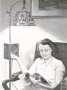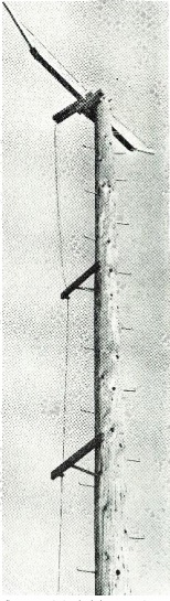
VHF Antenna at FCC Allegan, Michigan, monitoring station, 1944.
Seventy years ago, the November 1944 issue of Radio News carried a story of a phenomenon that was baffling radio engineers, and was under investigation by the FCC monitoring station at Allegan, Michigan. The station was reporting strange bursts from distant FM broadcast stations, then operating in the 42-50 MHz band. The FCC station had receivers tuned to the frequencies of distant stations, constantly making a record of the signal strengths as the distant stations came up out of the noise. The signals were bursts of a very short duration in the station’s signal strength. These bursts were rarely of a duration longer than a single spoken word or one or two notes of music.
The bursts have been observed at distances of up to 1400 miles, but were more common at distances of 300-700 miles.
The article was almost certainly describing meteor scatter. A letter to the editor of QST, November 1946, from Gurdon R. Abell, Jr., W2IXK, seems to be the first reference by a ham to the same phenomenon. He noted hearing bursts of signals during the Perseids meteor showers on 144 MHz, which coincided with bursts from New York HF stations inside his skip zone. He concludes, “if this observation can be relied upon, it means that 144-Mc. signals can be refracted by the stronger meteor trails,” and he seeks further corroborating evidence.
This letter was probably inspired by a January 1946 QST article by Oswald G. Villard, Jr., W6QYT. Villard detailed how to listen to meteors by monitoring short wave stations on 11, 15, or 18 MHz. A meteor would result in a signal being reflected, but with a doppler shift causing a change in frenquency. The two signals would result in a heterodyne, causing an audible whistle. Villard followed up with another article in QST for July 1947, but was still focused on the HF effects of meteors, the highest frequency investigated being 27 MHz.
Two follow-up letters to W2IXK’s appeared in QST in January 1947, from Villard, and also from Bruce Henke, W6TFJ, who noted a similar phenomenon on 10 meters. In April 1953, Villard, along with Allen Peterson, W6POH, wrote an article discussing the possibility of using “meteor scatter” for communications on 15 and 20 meters.
Between 1953 and 1956, VHF operators started to figure out the possibilities of this propagation mode. Many of these are detailed in the World Above 50 Mc column in October 1956.
With digital modes, able to make an entire exchange in less than a second, meteor scatter is now fairly routine. In the 1950’s, it required fast Morse code, and more than a little luck. It’s not impossible, however, with voice modes. From Minnesota, South Dakota is a difficult catch on 10 meters, since it’s well within the skip zone. I have South Dakota confirmed, and I’m pretty certain it’s courtesy of a meteor. During a 10 meter contest, I just happened to have the VFO on the frequency being run by W0SD in Salem, SD, a distance of 225 miles. (If you’re driving I-90 through South Dakota and wonder what those towers are as you pass Salem, now you know.) He was calling CQ, and he came up out of the noise with a booming signal. I quickly called, we made the exchange, and then he disappeared. He was audible for only a few seconds, and it was dumb luck that I was on his frequency for those seconds. I can’t think of any explanation other than meteor scatter for this contact.
Note: To view the QST articles linked above, you need to be logged in to your ARRL account.
Click Here For Today’s Ripley’s Believe It Or Not Cartoon