Category Archives: Radio history

Queen Elizabeth II, 1926-2022

PrincessElizabethQueen Elizabeth II of the United Kingdom died today at the age of 96.  She was preceded in death by her husband Prince Philip, the Duke of Edinburgh, Patron of the Radio Society of Great Britain.

She came of age during World War II, and it’s not surprising that her first public speech was on the radio.  In 1940 at the age of 14, the Princess addressed the children of Britain, especially those who were far away from home, having been evacuated to the countryside or the Empire or to America.

You can hear that speech here:

One of her last addresses was during the early days of the COVID lockdown, when she referred to that speech, and closed with the words of Vera Lynn’s “We’ll Meet Again.”


1937 Two Tube Broadcast/Longwave Receiver

1937SepPS11937SepPS3This gentleman, shown 85 years ago this month in the September 1937 issue of Popular Science, might be listening to a standard broadcast program. But chances are, he’s tuning the longwaves, listening to ships or aircraft beacons on what was then called the X-Band (not to be confused with the modern X band of 7-11.2 GHz, or the expanded AM broadcast band of 1610-1700 kHz).

The set used two tubes to cover 250-1650 kHz in two bands, with a tapped coil and a toggle switch to short out part of the coil for the higher frequencies. The circuit could be duplicated today, since there don’t appear to be any unobtainium parts. You wound the coil yourself, although it would take a bit of patience, since it consisted of 360 turns of number 32 wire carefully wound on a 1-1/4″ form.

Government weather reports were easy to tune in with the set, since they were transmitted on the A-N beacon frequencies. If you lived right on an airway, you would hear a continuous carrier. But more likely, you would hear either an A or an N in Morse code, indicating you were off to one side. Once a minute the station would send its call letters. Weather reports were broadcast on a regular basis.

In addition, lighthouse radio beacons consisted of one letter repeated for one minute. These were in clusters of three stations, and they would take turns sending a letter, allowing a ship radio compass to determine its position.

The article warned that, like all regenerative detectors, the set was capable of interfering with nearby receivers if improperly tuned. To avoid this, the article advised tuning in from the edge of the signal, and turning down the regeneration before tuning in the exact carrier frequency.

1937SepPS2


1942 Longwave Time Signal Receiver

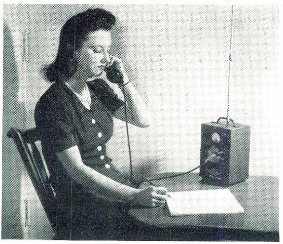
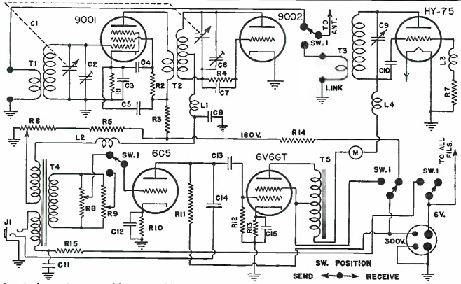
1942SepRadioNewsThe nondescript black box shown here is a longwave receiver from the September 1942 issue of Radio News.  (The instrument at the left is an Aerovox L-C checker, presumably there to show the scale.) Specifically, the receiver was part of the broadcast equipment of WCED radio in Pennsylvania, and was designed to pull in the time signals from the Naval Observatory from station NSS, Annapolis, MD, operating on 113 kHz. For a station in a place like Pennsylvania, just a few hundred miles from Annapolis, the shortwave signals were often unreliable, being in the skip zone. The longwave signals were reliable, with no fading. The Navy permitted their rebroadcast by local stations, on the condition that mechanical relays not be used, as they would add a delay to the time, which was accurate to within 1/10 second.

This receiver was superheterodyne, with an IF of 465 kHz. The detector was regenerative, and could copy the CW signals, which were then simply rebroadcast over the air at the top of the hour.

1942SepRadioNews2


1937 Portable Transmitter-Receiver

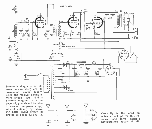
1937SepAllWaveRadioEighty-five years ago this month, the September 1937 issue of All Wave Radio carried the plans for this transmitter-receiver combination for portable or emergency use. The set had a built-in AC power supply, or it could be used with a 6 volt battery with the use of an external “Vibrapack” power supply, which was commercially available. It featured rugged construction on an aluminum chassis, and was housed in a portable phonograph case.

Interestingly, the article doesn’t even mention what band the rig is for, although 40 or 80 meters would be the most likely. The final choice would boil down to the choice of coils in the transmitter and receiver and, of course, the transmitter crystal.  The article calls for an antenna of 32-33 feet, so it’s a safe bet that the author, Myron Morris, W2IOJ, made his for 40 meters.

The transmitter consisted of a single 6L6, and was said to have an input power of 10-20 watts. The receiver used a 6K7 as regenerative detector, and 6F6 audio amplifier to drive either headphones or a speaker. The internal AC power supply used a 5Z4 rectifier.

1937SepAllWaveRadio2


1942 Blackout Receiver

1942SepPSEighty years ago this month, the September 1942 issue of Popular Science showed how to construct this two-tube battery operated receiver. The low power consumption made the set especially useful in case of a blackout, an ever-present wartime possibility.

The set consisted of a 3A8-GT triode-pentode which served as RF amplifier and detector. This went to a 1E7-G dual pentode, which served as the push-pull audio amplifier, driving a loudspeaker. For best volume, 135 volts was recommended (three 45-volt batteries), but excellent results could be obtained with just 90 volts. Because sets of this type sometimes had difficulty tuning the entire broadcast band, there is a trimmer in parallel with the tuning capacitor. This was adjusted to the particular part of the band to be tuned, and then stations were tuned in with the main dial.

Eighty years ago, people took things in stride, and most people considered electricity to be a luxury. If the power went out, whether because of a storm, or to blackout in case of air attack, people were able to continue their life with little interruption. And for those who put together this radio, they still had the luxury of radio, even with the power out.

These days, people view electricity more as a necessity and not a luxury. Ironically, though, it’s much easier to prepare for blackouts today. Things like batteries, flashlights, and portable radios are incredibly cheap. For some pointers on how to prepare for blackouts, see our earlier post. And for pointers on how to prepare for winter power outages (which might be a true emergency), see this post.

1942SepPS2

1942SepPS3


1972 KC4DX Navassa DXpedition

1972Aug73Fifty years ago this month, the August 1972 issue of 73 magazine devoted its cover and an extensive article to the May 12-15, 1972 KC4DX DXpedition to Navassa Island, a two-square-mile island nestled in the Caribbean between Cuba, Haiti, and Jamaica. The island is a U.S. possession, although also claimed by Haiti. Surrounded by cliffs on all sides, it has no beaches, and the only access by sea is a wire ladder dangling down from a platform cantilevered over one of the cliffs.

The magazine’s publisher, Wayne Green, had done a DXpedition to the island in 1958 with the call KC4AF, and when he caught wind of plans to go in 1972, he signed on as photographer.

The 1972 expedition used only three radios, a Swan 500C transceiver, as well as a pair of Heathkit SB303 receiver/SB401 transmitter. Two gasoline generators powered the stations, which operated for only 54 hours. The Swan transceiver was incapable of “split” operation. That, coupled with the fact that only modest antennas were used, hampered the operation somewhat, although 5500 contacts made it into the log.

In addition to the 73 article, which you can read at the link above, you can find this account, complete with some videos, by W4GKF.

At the time of the 1972 operation, the island was under the control of the U.S. Coast Guard, who still operated a lighthouse there. It was last activated in about 1997 until a 2015 DXpedition, K1N, again put it on the air. By this time, the island was administered by the U.S. Fish and Wildlife Service, which had traditionally been reluctant to allow civilians on the island. This, however, was arranged, and the operators and equipment were brought in by helicopter, since the famous ladder had been removed when USFWS took over administration. This time, 140,000 contacts were made, with 30,000 different stations. As you can see, I made it in the log in 2015:

k1nlog


1947 Meissner Brewster Model 6D

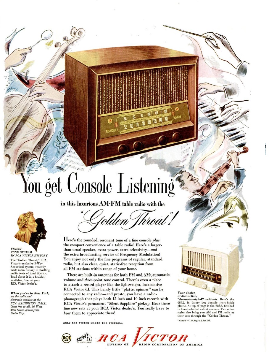
1947AugRSDSeventy-five years ago this month, the August 1947 issue of Radio Service Dealer featured this ad for Meissner radio’s “Brewster” line of radios, from Maguire Industries Incorporated, 936 N. Michigan Avenue, Chicago.  The ad showcased the company’s Model 6D, a table set “beautifully styled in rich ivory plastic.”  The set tuned the broadcast band as well as 5.75 – 18 MHz shortwave, and contained five tubes plus rectifier.


1922 Newspaper Radio Page

By a hundred years ago, it was already quite apparent that radio was, indeed, going to be a thing. This is clear from the radio page of the Washington Herald, August 27, 1922, shown above.

To show how vibrant the industry was already, the page contained nine ads, as well as the editorial content. The lead story, how to build the two-tube superregenerative receiver shown, was written by Thornton P. Dewhirst, a student at Washington Central High School. He reported using the hookup to pull in all of the local stations, as well as WSB Atlanta.


1947 “Last Ditcher” One Tube Transmitter

1948AugQSTIn recent years, the ARRL has billed Amateur Radio as being the thing that will get through “when all else fails,” but this is not a new concept. Seventy-five years ago this month, the August 1947 issue of QST described how to build a little transmitter called “The Last Ditcher.”

According to the author, QST Technical Assistant John Paddon, VE3BLZ, most emergency situations saw the bulk of amateur traffic carried by stations running car batteries, storage batteries, or gasoline generators.

“But suppose an emergency appeared under conditions such that it was utterly impossible to reach the scene except on foot and that all gear had to be back-packed. An example might be a plane crash on a mountain in broken country or a spot in a flood that could only be reached by wading.” In other words, a rig was needed when all else failed.

The solution was the one-tube transmitter shown here, using a 1J6G tube, mounted in a steel card index file box. Two flashlight batteries powered the filament, and the B battery could be anywhere between 22.5 and 180 volts. The author reported making a number of successful QSOs running 135 volts at 17 mA, which works out to an input power of just over 2 watts.  The set could cover either 80 or 40 meters.

According to the author, “with the ‘Last-Ditcher’ on the shelf you are ready to go should any emergency arise. Let it be hoped there never will be a call for it. When there is no emergency a surprising amount of fun can be had–if you have a yen to operate from a mountain top or a bush camp it is a lot easier to shove this little box in with the lunch. You won’t have to run leads into your car, unload storage batteries or drag out the gas putt-putt.”

The article didn’t mention which receiver you would take with you on foot, but as our readers know, there were many available options.  One good choice would be the “one tube flashlight” set we previously described.

1947AugQST2


Radios for Phonograph Dealers: 1922

1922AugTalkMachWorldA hundred years ago, phonograph dealers started to realize that radio was, indeed, going to be a thing. And if they wanted to remain profitable, they would have to start selling radios.

The August 1922 issue of Talking Machine World included a number of radio ads, of which this one was typical. The general theme was that if you wanted to stay in business, then you should start selling the other kind of talking machine, namely, the radio.

This one, from the Harpanola Company of Celina Ohio, itself a phonograph maker (and before that, furniture maker) was typical. The time to act was now, and you couldn’t wait for the horse to be stolen before locking the barn door. There were radio stores out there, but the ad admonished the phonograph dealer to “let the radio stores sell the experimenters and the boys.” The phonograph dealer would be the place to go for those who wanted a “drawing room” radio, in a well-finished cabinet. The company promised that it would “show you the way to introduce cabinet radios successfully. The profits and volume of sales are going to set new records in money-making.”