Category Archives: Radio history

1953 Novice Transmitter

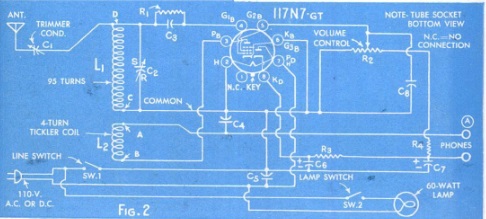
1953SepRadioElec2Seventy years ago this month, the September 1953 issue of Radio-Electronics carried the plans for this economical two-tube transmitter for the novice. It ran 35 watts input power, which the author, Richard Graham, W1VJV, acknowledged was less than the legal limit of 75 watts. But the advantage was cost. At the lower power level, common TV parts could be used, making it singificantly less expensive. And on the receiving end, the difference was only half an S unit, which wasn’t even discernible by the human ear.

The rig employed a 6C4 as Pierce oscillator, driving a 6BQ6-GT final. With the coils shown, it could tune both 80 and 40 meters. At the time, the Novice did not have privileges on 40, but would be ready the moment they upgraded to General.

1953SepRadioElec3


1938 Two Tube Regen

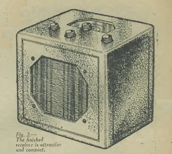
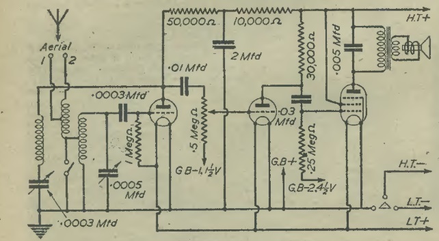
1938SepRadioNews2Eighty five years ago this month, the September 1938 issue of Radio News carried detailed construction details for putting together this two-tube shortwave receiver. It used a 1B4 as regenerative detector, followed by a 1F4 as audio amplifier.

The set tuned 160 through 10 meters, and the author advised that the beginner should start on 160 meters, since most signals will be relatively local and easy to tune in. He also gave pointers on which bands would work best at different times of day.

The article concludes by noting that once the reader becomes acquainted with the operation of the set, it would be a reliable and consistent way to bring to your headphones most of the DX signals of the world.

1938SepRadioNews1


1948 3-Tube Shortwave Receiver

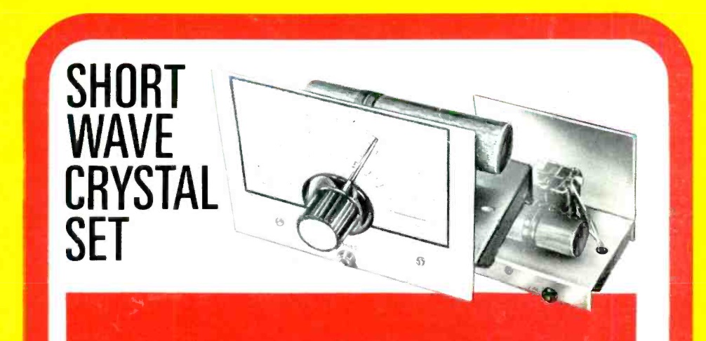
1948SepPracWirSeventy-five years ago this month, the British Practical Wireless carried the plans for this handsome three-tube shortwave receiver. It used homemade coils. It would drive a speaker, but for pulling in weak stations, or for amateur radio use, headphones could be used.

The coils are mounted under the chassis, and were switchable from the front panel.

1948SepPracWir2


Emerson 747 Pocket Radio, World’s Smallest Radio: 1953

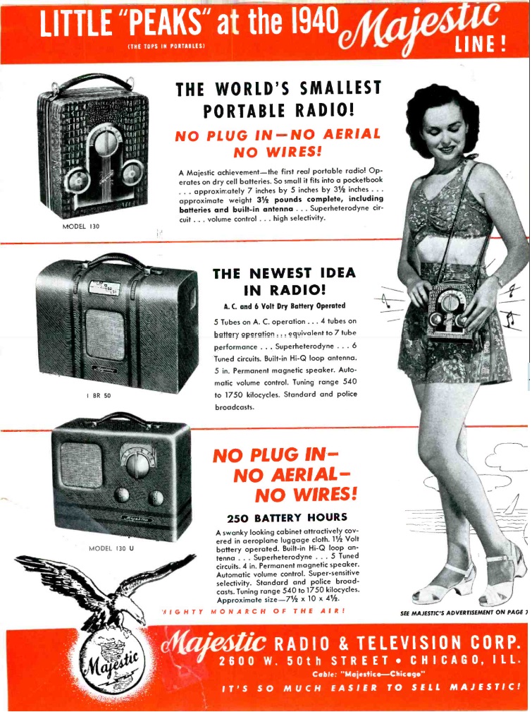
Emerson7471953SepRadioElecAt first glance, the radio above appears to be a transistor radio from the late 1950s or early 1960s. But it’s not. While the transistor had been invented when this radio came out in 1953, it didn’t use any. Instead, it’s a four-tube radio, employing flat miniature tubes. While most often used in hearing aids, this radio made use of those tubes, and for $40, you could have what was rightly the world’s smallest radio. While other radios might have been smaller, they were essentially novelties, requiring headphones and often an external antenna. This four-tube superhet pulled in the stations with an internal ferrite antenna, and the sound from the 2-1/2 inch speaker could be heard across a large room.

The announcement at left appeared 70 years ago this month in the September 1953 issue of Radio Electronics. The ad above is courtesy of Joe Haupt from USA, CC BY-SA 2.0, via Wikimedia Commons. The set retailed in 1953 for $40. You can learn more about it and view a pristine example at the video below.


Radio in the Schools: 1938

1938SepRadioCraftThe New York city high school students shown above are presenting Macbeth over the airwaves of WNYC. They are featured in an article in the September 1938 issue of Radio Craft, which notes that a new “R” has found its way into education. In addition to Reading, ‘Riting, and ‘Rithmetic, the schools now included Radio.

1938SepRadioCraft2The station presented two educational programs per day–one for elementary students, and one for the high schools. The fifth graders at P.S.92, Bronx, shown here are listening to one such program, which was picked up by an ordinary receiver in the room. Not all schools were yet equipped with radio, but the plan was for every classroom in the school system to have its very own radio in the near future.

The students appearing in the programs were selected by audition, and the magazine noted that there was no shortage of volunteers.

The same issue of the magazine also carried an editorial by Hugo Gernsback, who opined that schoolroom broadcasting would afford deserving young boys and girls and opportunity for self-expression never before available. He also reminded his readers that there was a very decent profit to be made by the enterprising radio man who goes after the business in education.


Kadette Autime Clock Radio, 1938

1938SepRadioRetailingShown here is the earliest clock radio I’m aware of, the Kadette Autime, from the September 1938 issue of Radio Retailing. According to the ad, the combination of clock and radio working together was a veritable miracle! You could, for the first time ever, wake to music instead of a raucous gong. You could also use it to avoid missing a favorite program. The set would play for 90 minutes.

The clock was said to rival the costliest in accurate timekeeping, and the radio was said to have superb tone, all in a beautiful rich burl walnut cabinet.


1963 Student Experimental Licenses

1963SepPEShown here, in the September 1963 issue of Popular Electronics, is Albert Pabin (I believe with the headphones) and two other students demonstrating an audio console by using it during an actual broadcast. Pabin was a ninth-grade student at Utica Free Academy, Utica, NY. His science project was the console he designed and built, and he wanted to demonstrate it under actual broadcast conditions.

To do so legally, he procured an experimental license from the FCC, and was able to go on the air, on 27 MHz, with the call KF2XGJ. According to the magazine, the FCC rules made provision for student experimental licenses for students, seventh grade and above, who had “a good idea of what he is trying to show, and that he have older and more knowledgeable persons available to help him in case of difficulty.” In particular, “the FCC believes that a student’s instructors are fair judges of his motives and sincerity, and looks favorably on projects endorsed by an instructor.” Notice to the FCC Engineer-In-Charge for the district was also required.

The application required various technical descriptions of the transmitter, as well as a statement from the principal or faculty member, on school letterhead, stating that the project had he approval of the school. The magazine noted that the frequencies generally available were 27.23-27.28 MHz., 460-461 MHz, 462.525-467.475 MHz, and 2450-2500 MHz. Power was often (but not always) limited to 5 watts.

While experimental licenses are still provided for in Part 5 of the FCC Rules, there is no specific provision today for student experimental licenses.


1943 Barb-Wire Telephone

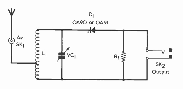
1943SepRadioCraftEighty years ago this month, the September 1943 issue of Radio Craft carried this circuit, dubbed the “barb-wire telephone.” It was sent in to the magazine by one Fred H. Randolph (from another submission to the magazine, apparently of Booneville, AR), who reported using it to communicate with a friend three miles away, courtesy of an iron fence wire. The circuit is nothing more than an audio amplifier using a carbon button mike, and puts out enough power to drive a speaker at the other end of the circuit, where an identical unit is located.


Courtney’s Radio Service, Stratford, CT, 1943

1943SepRadioRetailingThe cover of Radio Retailing, September 1943, was a tribute to the WWW. No, it had nothing to do with the internet–it was honoring Women War Workers, such as Mrs. Wallace Courtney of Courtney’s Radio Service, Stratford, CT.

Before the war, the shop was run by her husband, who had recently taken a job in a war plant installing radios in planes. Despite shortages of both parts and help, Mrs. Courtney, also the mother of a 12 year old boy, kept sets moving along as fast as possible.

The magazine noted that Mrs. Courtney was typical of a lot of American wives and mothers, who without any fuss or furor, had stepped calmly into their men’s places for the duration.


1963 Homemade Microphone

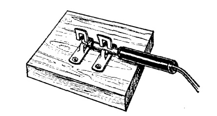
1963SepEIWe’ve previously shown (here, here, here, and here) other homemade microphones. This idea for a carbon mike appeared in Electronics Illustrated, September 1963. The mike element itself is made of carbon granules. These are obtained by cutting open an old carbon-zinc battery and removing the carbon rod.
You grind them up finely with a file, or by using a metal rod as a rolling pin. The resulting granules are placed in a plastic bottle cap, and wired to a battery and transformer. Almost any type of transformer can be used, either an audio transformer or power transformer. The larger winding is connected to the mike element. The cap is set on top of a paper tube 2-3 inches in diameter, into which you speak.