Category Archives: Radio history

1954 Code Oscillator

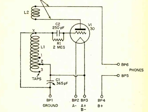
1954FebQST11954FebQSTThis schematic for a code practice oscillator appeared in QST 70 years ago this month, February 1954. The observant reader will notice that something seems to be missing.

That’s right. There’s no apparent source of B+ power. The only power connection is to the filament of the tube. But it works anyway! According to an editor’s note, the circuit shows 0.2 volts between the cathode and plate, derived from the initial velocity of the electrons.

According to the same note, the only other circuit that works without any apparent plate voltage is a Tri-Tet crystal oscillator,  This is explained in more detail in an article in the May 1941 issue of QST. According to that note, the oscillator “will run merrily without plate voltage from an external source so long as the circuit is complete.”

This code oscillator was designed by long-time ARRL staffer Lew McCoy, W1ICP, who then held the title of Technical Assistant. He noted that the electric buzzer was the traditional method, but “if you don’t live alone, the sound of an electric buzzer may soon grate on the nerves of the family or neighbors.” This inexpensive circuit allowed practice while still preserving peace at home.

The novel method of powering the oscillator meant that it could be built for less than six dollars, less than half the cost of commercial code oscillators. And after licensing, those parts could undoubtedly be put to use in other projects.

McCoy noted that while the circuit worked with all 6J5 tubes he tried, it was possible that a particular tube might not. In that case, the advice was to try another. He noted that the 6F6 pentode he tried, with plate and screen tied together, also worked.

The oscillator took care of the beginner’s need for sending practice. For receiving, he pointed out the W1AW code practice sessions, but also included a list of other stations with scheduled code practice. Many of these were operating on 10 meters. For example, W0BOL was sending code practice on 29.2 MHz Tuesday and Wednesday evenings from 1130 Delaware Avenue, St. Paul, MN.

1954FebQST3


1944 Automatic Gun Director

1944RadioCraft11944RadioCraft2Eighty years ago this month, the February 1944 issue of Radio Craft gave some description of the automatic gun director system illustrated here. The system consisted of a computer (undoubtedly analog) that directed the gun exactly where to fire. The path of the plane was plotted by two telescopes, whose operators kept the plane in the cross hairs for a few seconds, to plot the aircraft’s location, speed, and direction. Height was measured in a similar manner, and the computer had inputs for wind direction and velocity, muzzle velocity, and air pressure. The result was a gun that was able to aim itself to the spot where the plane would be when the shell arrived.


1949 Radio-Intercom

1949JanPMThis combination radio-intercom system was the latest thing 75 years ago. It could be used as a regular broadcast receiver, from either its own speaker, or the extension unit in another room. And at the push of a button, it could be used for two-way communications. The set had four tubes, said to be quick heating.

It appeared in the January 1949 issue of Popular Mechanics.


R.C. & L.F. Hall, Houston, 1944

1944FebRadioRetailingThe duo behind the counter here are Dick Hall, W5EIB, and his wife Lillian Hall, W5EUG, owners of R.C. & L.F. Hall, 1015 Caroline St., Houston, Texas.

Their business began when they found a lack of interest by local dealers for hams, and Dick began stocking a few parts in his home. As the stock started to overtake their entire house, they moved to a downtown location. As they anticipated American entry into the war, their business focused on industrial and marine parts. When war came, they knew the whereabouts of most amateur transmitters and receivers in the area, and facilitated sales of that equipment to the military.

The Halls discovered that dealers and hams don’t really mix. The dealer, seeking marine and industrial parts, knew just what he wanted, whereas the hams wanted a place that talked their language. They anticipated a big future for their business after the war, as hams came on the air, and as FM and TV stations would create new markets.

The picture and accompanying article appeared in Radio Retailing, Feburary 1944. This eBay listing shows a 1946 ad for their business, which by then had locations in Beaumont, Dallas, and Galveston, in addition to the Houston store, which was then at 1306 Clay Avenue.


The House Wired For Radio, 1939

1939FebRadioCraftEighty-five years ago, the February 1939 issue of Radio Craft shows how to wire your house for radio. And like Mr. Green, you could be serene knowing that there was one in every room. Actually, there was only one radio, a top-of-the-line RCA Victor model U-130. Speakers were mounted in each room. But in addition, the set allowed the use of a wired remote control, so controls were mounted on the walls of most rooms. But if walking over to the wall proved too stressful, there was also an armchair remote, which could be plugged in to a nearby socket.

The installation also incorporated a set of Model 446 Aristocrat “TELECHIMES” by General Kontrolar company, Inc., which could be used to elegantly page family members throughout the house.


1939 British One-Tube Regen

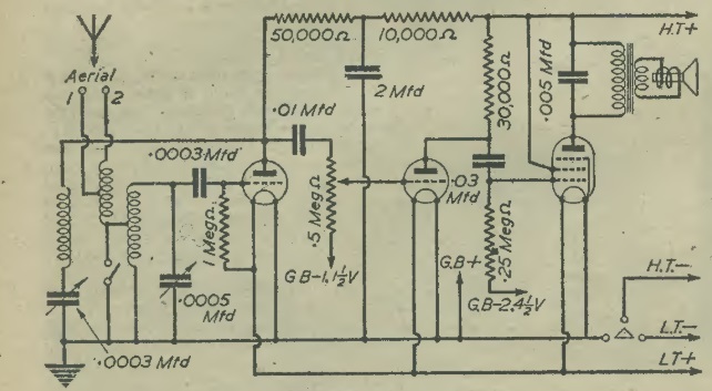
1939FebPracMechThe plans for this one-tube–er, I mean one-valve–regenerative receiver appeared 85 years ago this month in the January 1939 issue of Practical Mechanics.

The article begins by noting that “the small receiver is apt to be despised in these days of 7 and 8 -valve superhets, there is still a very wide field of application for the simple one-valver. Many schoolmasters, for in- stance, have asked for details of a set which may be used as a demonstrating model, either for handycraft instruction, or to explain many of the theories underlying modern radio technique.”

The circuit relies upon a pre-made coil, which is no doubt unobtainium these days. But the article does describe how to make a very similar coil, which can be used with slight modification of the circuit. Either way, the set did tune both longwave and mediumwave bands, thanks to a band switch which shorted out the longwave portion of the coil. The set uses a D210, which is a British model, but almost any triode would probably work well.

1939FebPracMech2


1974 Digital Watch

1974JanPEFifty years ago, the hobbyist with nimble fingers and a sharp eye could have their own digital watch, thanks to this project in the January 1974 issue of Popular Electronics.

If you bought one, it would set you back $200, but you could make your own for about $80. The construction article gave the source for the case, you could make the small PC board, or you could buy the whole thing as a kit. If the tip on your soldering iron wasn’t small enough, the article suggested attaching a piece of copper wire and filing down the end. Accuracy was said to be several seconds a month.


1949 Combination Receiver/Signal Generator

Screenshot 2024-01-12 12.43.23 PMThis utilitarian-looking three-tube British device appeared in Practical Wireless 75 years ago this month, January 1949. It has considerable utility, as it functions as both a regenerative receiver and signal generator.

The regenerative receiver, of course, causes oscillation that can be radiated through the antenna jack. But this circuit does one better, because it turns the audio amplifier into an oscillator, which modulates the signal. Therefore, when working on another piece of equipment, you have a handy source of tone modulated RF. And when you’re done troubleshooting your other device, you can tune in programs from 3000 to 10 meters. Thanks to the second harmonic, you can use it as a signal generator up to five meters.

Screenshot 2024-01-12 12.44.29 PM


1924 One-Tube Loudspeaker Set


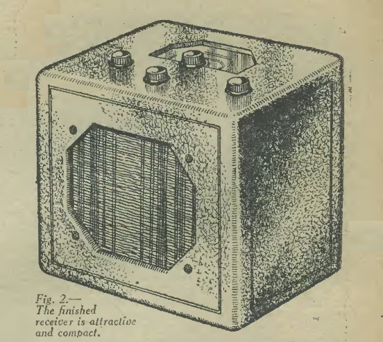
1924JanPSThe plans for this handsome one-tube receiver appeared a hundred years ago this month, in the January 1924 issue of Popular Science. The regenerative set, when used with a high-quality loudspeaker, was capable of producing volume to fill a large room, with but a single tube. The secret was the antenna coil, which served as an autotransformer to boost the signal in the regenerative circuit.

The set was both sensitive and selective. When tested in New York City, within a couple of miles of some strong broadcast stations, it easily pulled in more distant stations. And with a 100 foot antenna, the author reported pulling in Chicago with loudspeaker volume.

1924JanPS2


1944 Intercom

1944JanPSEighty years ago, there was a war going on, but in his workshop, this gentleman had a power supply capable of putting out 250 volts and six volts. He also had a few tubes lying around, so he put together this audio amplifier, which he used as an intercom. The master station was down in the shop by his power supply, and he mounted a speaker in the kitchen. It was fed with a single wire, with water or steam pipes serving as the second conductor.

From the shop, he could monitor what was going on in the kitchen. And when his wife announced that lunch was almost ready, he let her know he was on the way up. The amp could also be used for a phonograph, as shown in the schematic.

The circuit appeared in the January 1944 issue of Popular Science.

1944JanPS2