Category Archives: Conelrad

1954 CONELRAD Alarm

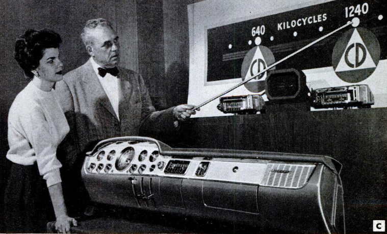
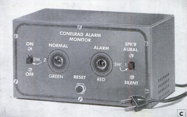
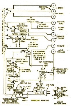
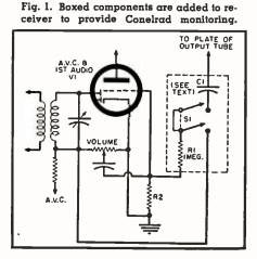
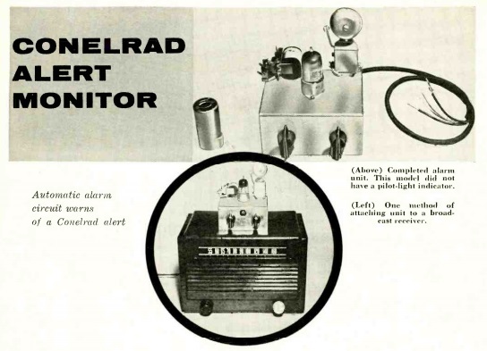
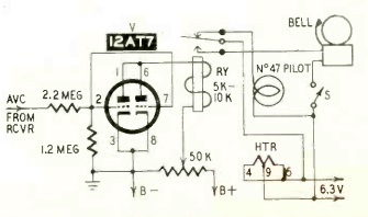
1954AugPMSeventy years ago this month, the August 1954 issue of Popular Mechanics showed how to put together this CONELRAD monitor for the ham.  This one was more extravagant than most.  It was hooked into the AVC circuit of a broadcast radio, and would trigger when the station being monitored left the air.  In addition to setting an alarm, the author had it wired to automatically shut down the transmitter and switch to receive.

1954AugPM2


1942 Air Raid Alarm

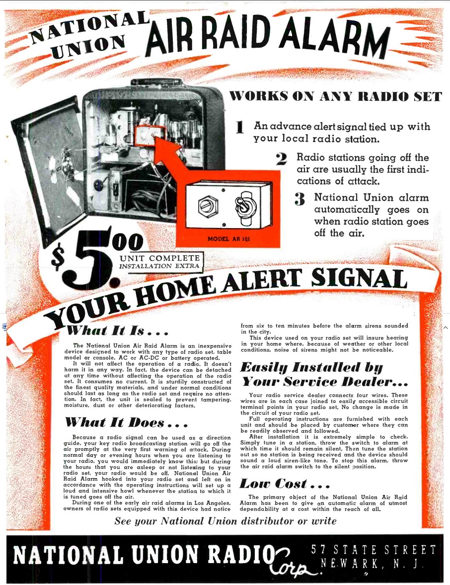
1942JuneServiceEighty years ago this month, the April 1942 issue of Service magazine carried this ad for the Model AR-101 Air Raid Alarm from National Union Radio Corp., 57 State Street, Newark, NJ.

For $5 plus installation, the small device was attached to “any type of radio set,” although I suspect the radio in question had to be a superheterodyne with AVC. But since most five-tube radios of the time fit that description, it was pretty close to “any type of radio set.”

During an air raid, radio stations would go off the air, so as not to serve as a beacon for incoming aircraft. According to the ad, the stations going off the air “are usually the first indications of attack.” The ad noted that during the early air raid alarms in Los Angeles, owners of radios with this device would have received warning six to ten minutes before the sirens sounded. And inside the house, the sirens might not be noticeable.

When the station went off the air, the radio equipped with this alarm would emit a “loud siren-like tone.”

According to the ad, the alarm was “sturdily constructed of the finest quality materials, and under normal conditions should last as long as the radio set and require no attention. In fact, the unit is sealed to prevent tampering, moisture, dust, or other deteriorating factors.”

And I suspect it was sealed for another reason–to conceal just how simple the circuit was, especially given the $5 price tag. The image in the ad shows a tiny box, with only a switch and what appears to be a potentiometer. The device had four wires that connected to easily accessible points in the radio.

1957ConelradI haven’t been able to find any more information about this device, but I suspect it’s very similar or identical to the 1957 “CONELRAD The Easy Way” circuit we featured previously. In that circuit, shown here, when the radio is set into the alarm mode, the AVC voltage is used to bias the first audio tube to cut-off, rendering the radio silent. But if the station goes off the air, the AVC voltage is zero, and the first audio stage comes back to life. The output from the final audio amplifier is fed back through the capacitor, resulting in feedback, or what the ad would call a “loud siren-like tone.”


1962 Fallout Shelter Antenna

1962FebPMSixty years ago this month, the February 1962 issue of Popular Mechanics carried this hint for using an outdoor antenna in the fallout shelter. The magazine noted that the shielding required for fallout protection could also shield against vital radio broadcasts. Since most radios didn’t have an external antenna jack, the magazine showed how to add one. A small coil was placed over the loopstick antenna, and that coil was hooked to an outdoor antenna. For optimal reception, you would tune in a station close to 640 or 1240, the CONELRAD frequencies, and slide the coil along until the signal was strongest. At that point, you would add a little cement to fix the coil in place.

The antenna could be unplugged when in normal use, but quickly put to work in the shelter in time of emergency.


1962 Allied “DX’er” Regenerative Receiver Kit

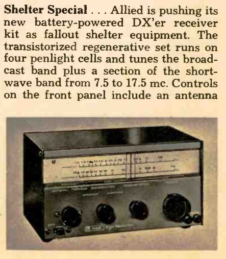
AlliedDXerThe May 1962 issue of Electronics Illustrated showed this smart-looking regenerative receiver kit from Allied, the Knight Kit “DX’er”, a three-transistor regenerative receiver for the broadcast band and one shortwave band.  It operated with four penlight cells, and Allied touted the receiver as ideal for the fallout shelter.

It does seem like an ideal choice.  The set undoubtedly had a low current drain, and with a few extra sets of batteries stored away, it would probably be a good source of information for the duration of the stay.  The standard broadcast band could be used to pull in the local CONELRAD station, and the shortwaves would probably give some indication of what was going on in the outside world.

According to the magazine, the kit sold for $19.95, but in the 1963 Allied catalog, the price had been reduced to $14.95.

National Emergency Alarm Repeater: 1961

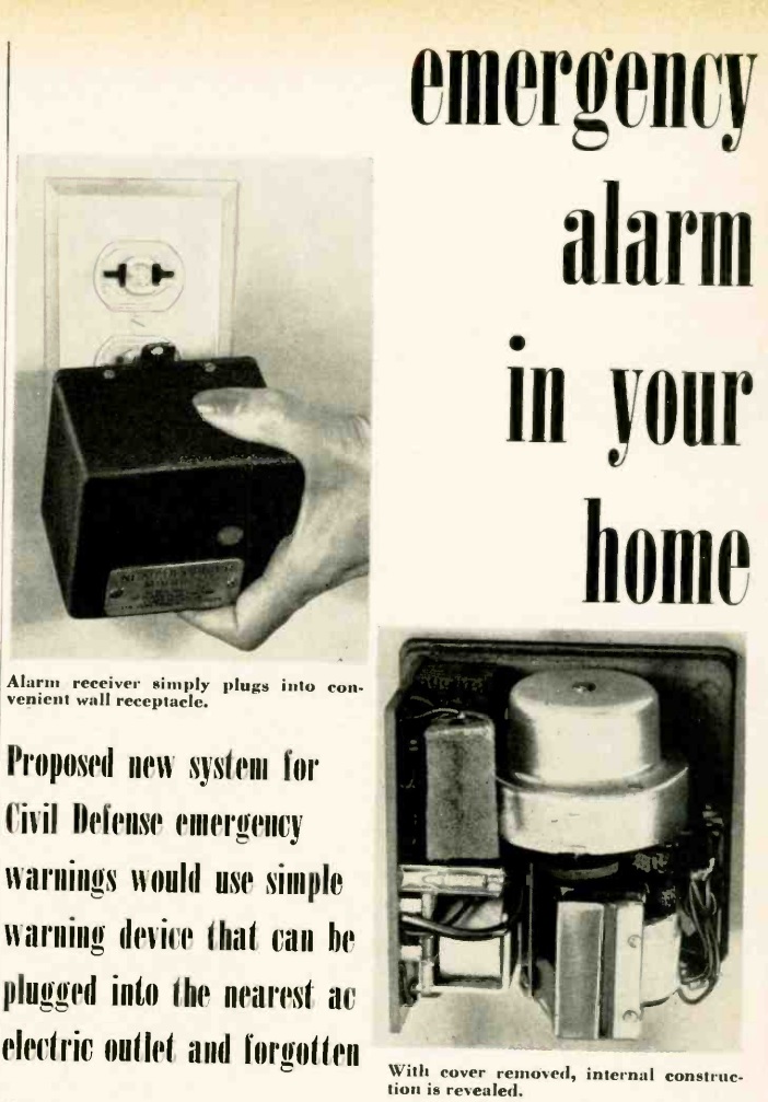
1961MarRadioElecOne of the great challenges of civil defense planners was alerting the public to an imminent nuclear attack. Sirens could be effective outdoors, but it was unlikely that people indoors would be able to hear them. One possible solution is discussed in the March 1961 issue of Radio-Electronics: NEAR, the National Emergency Alarm Repeater.

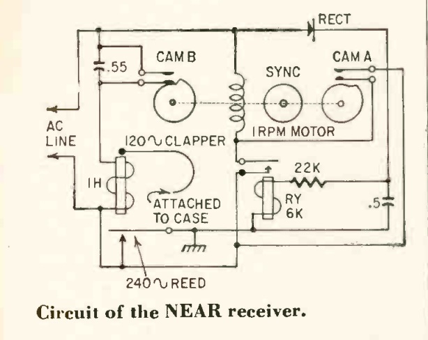
Three methods had been considered: telephone lines, power lines, and radio. The technical challenges for using the telephone network for simultaneously alerting the entire population were too difficult to overcome, and not everyone had a phone. Radio was a possibility, but radios were turned off many hours of the day, and especially at night. NEAR took advantage of the power grid. With only a few hundred repeater stations, a 240 Hz signal of about a volt could be superimposed on the line, and the receiver shown here was a clever electromechanical method of picking up that signal and sounding the alarm.

The home NEAR until shown here would be plugged in and forgotten by the homeowner until such time as there was an attack. It included a resonant circuit consisting of a 0.55 uF capacitor and 1 henry coil, with a tuned frequency of 240 Hz. To avoid false alarms, there was a time delay in the form of a 1 RPM motor. If the incoming signal were less than 10 seconds long, then the motor would simply reset and continue listening for a signal. But after 10 seconds, the motor would trip a clapper which used the outside of the device’s case as a sounder. The unit would emit a loud annoying noise which would alert the homeowner to the missiles that were incoming.

1961MarRadioElec2


Hammarlund Receiver at WCCO-TV, 1970

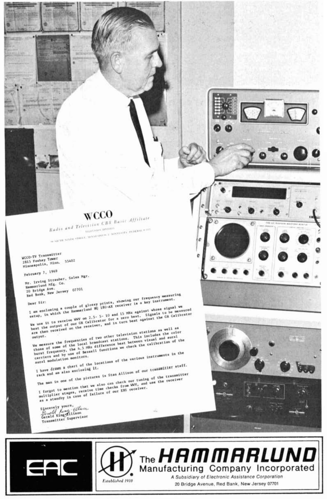
1970SeptHamRadioShown here in this Hammarlund ad from the September 1970 issue of Ham Radio magazine is part of the equipment of WCCO-TV in Minneapolis, whoss transmitter was then located in the Foshay Tower. The station had a Hammarlund HQ-180-AX receiver mounted on the rack as part of its frequency measuring equipment. The receiver was used to tune in WWV to zero beat the station’s calibrator. Then, signals were received on the receiver and beat against that calibrator.

The receiver was also used to check the tuning of transmitter multiplier stages, to receive time checks from WWV, and as a backup Emergency Broadcasting System receiver.

Shown in the picture is transmitter engineer Stan Allison, and the letter to Hammarlund describing the setup is penned by transmitter supervisor Gerald King Ellison.


1960 CONELRAD Monitor

1960JanRadioElecThe plans for this CONELRAD monitor appeared in the January 1960 issue of Radio Electronics magazine. As part of the nation’s civil defense structure, the CONELRAD system was designed to alert Americans to an incoming attack, but also make sure that broadcast signals did not serve as beacons for incoming bombers.

To prevent this from happening, all radio stations ceased broadcasting. Selected stations then resumed broadcasts, but only on two frequencies, 640 and 1240 kHz, in order to confuse the navigators of those incoming bombers.

1960JanRadioElecSchematicWhen the station first left the air, this would serve as the first warning to the public. And this device sounded a bell when the monitored station left the air. In some more remote areas, a more sensitive and selective receiver might be required. But in most areas, the ubiquitous “All American Five” receiver could be used. This alarm tapped into the receiver’s AVC circuit. If the incoming carrier disappeared, the bell would sound.


July 20, 1956 CONELRAD Test

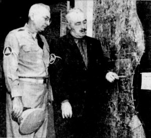
Milwaukee Civil Defense Director Don E. Carleton and Col. Anthony F. Levno assess damage after simulated attack on Milwaukee. Milwaukee Journal, Jul. 20, 1956.

Milwaukee Civil Defense Director Don E. Carleton and Col. Anthony F. Levno assess damage after simulated attack on Milwaukee. Milwaukee Journal, Jul. 20, 1956.

Today marks the 60th anniversary of what was, as far as I’ve been able to determine, the only nationwide test of CONELRAD, the system designed to give Americans emergency information about a nuclear attack.

As I wrote in a previous post, all radio and TV broadcast stations in the U.S. left the air at 3:10 PM Eastern Time.  Designated stations came on the air on 640 or 1240 kHz, alternating between transmitters to confuse enemy bombers.  In some cities, such as Milwaukee, local exercises were conducted in conjunction with the CONELRAD test.  In the photo shown here, civil defense planners are examining the hypothetical ruins of Milwaukee.

Click Here For Today’s Ripley’s Believe It Or Not Cartoon


1954 High Gain Low Drain Portable

RadioElectronics1954March

The plans for this “high gain, low drain portable radio” appeared in the March 1954 issue of Radio Electronics magazine.  It appears to be a good performer, but it was designed both for performance and low battery drain, and the author explained why:

When anybody anybody mentions “portable radio,” most of us think immediately of the entertainment it can provide.  The Set can go with us on picnics, vacation trips, and boat rides. We can enjoy ball games, national events and all our favorite programs while we work, play, and travel. But there is a serious side to this matter. In these days of H-bombs and supersonic jets, a portable radio might mean the difference between life and death. If that terrible day should ever come when air-raid sirens wail for real, the Conelrad system will go into effect. If worst comes to worst, if power goes out and wires down, civil defense messages and other essential communications will continue. In such an emergency, a portable radio can become a very important item.

With that in mind, the key design factor was low battery drain. A few years later, transistors would make that goal easy. But the current transistors on the market, while suitable for low-powered audio, weren’t yet ready for use with RF. Therefore, the design of this set was a hybrid–it contained two tubes, a 1E8 serving as oscillator and mixer, with a 1AD5 serving as IF amplifier. Then, solid state took over, with a 1N34 diode as the detector, and two CK722 transistors providing enough audio amplification to drive a speaker. For more distant stations, a headphone jack was provided.

Because of the hybrid design, the set required three batteries, but they were all set up to minimize current draw. The transistors were powered by 4.5 volts, provided by three dry cells. The filaments were powered by another 1.5 volt dry cell, but the author noted that these could be run on a battery so low that it was no longer useful for a flashlight. In addition, there was a potentiometer in series with the filaments. This would serve, to a certain extent, as a volume control. But more importantly, it would allow the filament current to be set to the lowest possible position.

The B+ for the tubes was provided by a 45 volt battery. Here, another battery saving trick was employed. The set contained a switch for local/long-distance. For strong local stations, a 56k resistor was switched in series with the B battery. This reduced the B+ current to only 50 microamps, just barely enough to keep the RF section running. For more distant stations, this resistor was bypassed, and the tubes ran on the full 45 volts, drawing about 1.6 mA.

The author reported that the set worked well with local stations, even in a skyscraper, or even in a subway or tunnel. He reported pulling in stations as far as 500 miles away with the telescoping antenna, normally designed for use as an automobile antenna.

RadioElectronics1954MarchSchematic

Click Here For Today’s Ripley’s Believe It Or Not Cartoon


1955 CONELRAD Monitor at WRFD

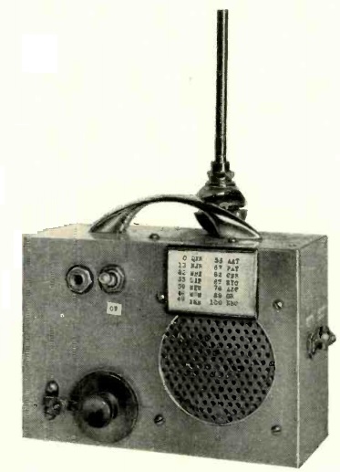
1955WRFDConelradFrom 1951-1963, U.S. broadcast stations were required to participate in CONELRAD, a system designed to alert the public to enemy attack, but also deprive enemy bombers of radio signals which could be used for navigation purposes.  Under a CONELRAD alert, all stations would cease broadcasting on their normal frequencies. Designated stations would switch to broadcasting on either 640 or 1240 kHz.  The result would be that listeners would be able to hear alerts, but enemy bombers would hear only a confusing jumble of signals on those frequencies.

For the system to work, each station needed an alarm.  For smaller stations, this would consist of an alarm tuned to another station in the area.  If the primary station went off the air, then the smaller station would be alerted.  If it turned out to be an actual alert, they would need to leave the air or switch to their designated frequency.  Alarms were available commercially for broadcast stations, and simpler models were also available for hams, who were later required to participate in CONELRAD.  Many hams built their own, and there were many plans published over the years.  Sixty years ago this month, the October 1955 issue of Radio Electronics magazine carried the plans for the unit shown here, which was in use at WRFD, a Worthington, Ohio, 5000 watt daytime only station affiliated with Fram Bureau Insurance, with a format aimed at the agricultural market.

The author of the construction article was Harold Schaaf, the station’s chief engineer, who noted a critical defect in many of the existing CONELRAD alarms.  Most of them depended on a normally open relay which would close in case of an alert.  If the alarm circuit failed for some reason, there would be no relay action.

Schaaf noted that “such a system cannot be considered reliable, since it can go out of order without the operator knowing it.” Schaaf’s circuit instead included a relay that remained energized during normal operation. In the case of a circuit fault such as a failure of one of the tubes, the relay would de-energize, which would cause the alarm to sound, requiring the station operator to investigate. The result was what the title of the article described as a “failure-proof CONELRAD alarm.”

Like most other CONELRAD alarms, this one was hooked to the AVC circuit of a superheterodyne receiver tuned to the station being monitored. As long as there was an AVC voltage present, the alarm would remain silent. If the monitored station went off the air, the AVC voltage would disappear, which would trigger the alarm, which could consist of an external bell.

Click Here For Today’s Ripley’s Believe It Or Not Cartoon