Monthly Archives: February 2020

1960 One-Tube Shortwave Tuner

1960FebEI1
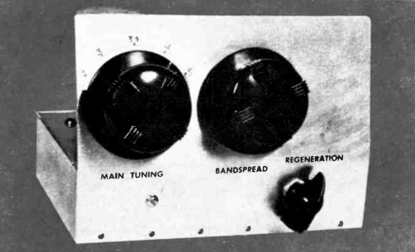
Sixty years ago this month, the February 1960 issue of Electronics Illustrated carried the plans for this one-tube regenerative shortwave tuner. The article was part 6 in the magazine’s build-it course, and the new tuner was designed to plug into the existing projects, which already included AM and FM tuners. For that reason, this receiver contains no power supply or audio amplifier. The cord with the 8-pin plug was keyed to fit the rest of the project, and the shortwave tuner took the place of the FM tuner.

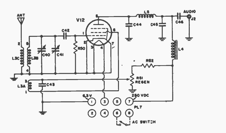
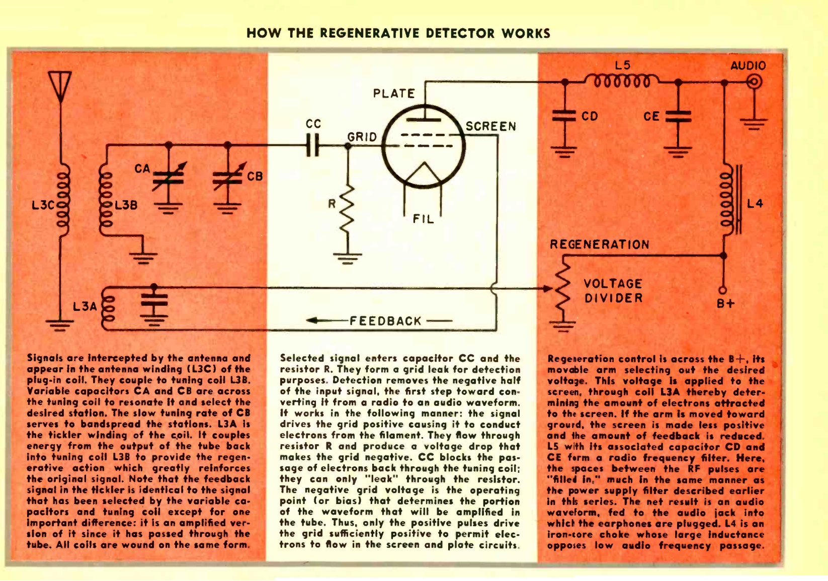
The circuit used a 6BC5 tube. One notable feature is that the regeneration was taken from the screen grid of the tube, rather than the plate. The regeneration control was a voltage divider which varied the positive voltage to the screen.

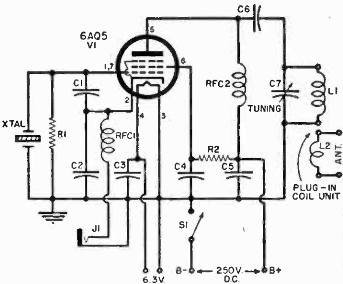
Since the article was part of a course, in addition to the exact schematic diagram, it also included a simplified diagram along with an explanation of each part of the circuit.  From most browsers, click twice on the image for an enlarged version.

1960FebEI3

Here is the actual schematic for constructing the receiver:

1960FebEI2


1950 One Tube Loudspeaker Set

1950FebRadioElec

This little broadcast set looks nondescript, but it was also something of a holy grail. As the February 1950 issue of Radio Electronics put it, “the one-tube loudspeaker receiver has long been the goal of constructors and experimenters.” And this set fits the bill. And as an added bonus, the addition of a single capacitor turned it into an excellent code practice oscillator.

The circuit, using a 3B7 tube, is described as a “special type of utraudion with a certain amount of superregeneration.” An outdoor antenna was recommended, but near powerful stations, the article noted that 25-50 feet were adequate. In remote areas, a hundred feet might be necessary.

The set used a permeanility tuner, which is likely unobtainium. However, the circuit could probably be modified to use a fixed inductor and variable capacitor.

1950FebRadioElecSchem


1955 One Tube Transmitter

1055FebPESixty-five years ago this month, the February 1955 issue of Popular Electronics carried the plans for this CW transmitter especially designed for the Novice. The rig used a single 6AQ5 tube to put out a signal on the 80 or 40 meter bands. Tuning up was accomplished by using a 6 volt bulb attached to a 1-1/4″ loop of wire. This was held near the transmitter’s coil and the rig tuned for maximum brightness.

To keep the circuit as simple as possible (and keep hum producing components at bay), the transmitter did not contain its own power supply. Instead, it required about 250 volts DC at 1 amp. “Most experimenters keep a small power supply of this type on hand for general use.” For those who didn’t, the magazine suggested that they were cheaply available as surplus. For portable use, batteries could even be used.

One interesting feature was the use of an octal tube socket for the crystal socket. The pins were such that a crystal would fit. The unused pins were used as a terminal strip for other components.

1055FebPEschematic

1055FebPEpictorial


Doorbell First Aid: 1945

1945FebPS21945FebPSThe woman shown above is fixing her doorbell, courtesy of instructions 75 years ago in the wartime February 1945 issue of Popular Science. The magazine explained the exasperation that would result from a non-functional or intermittent doorbell, but pointed out that even a novice, with almost no equipment, could tackle the job of getting the dead doorbell back on its feet. The troubleshooting process was broken down into four categories: testing the source of current, testing the button, testing the bell, and testing the wiring for shorts.

1945FebPS3It then laid out the procedures for each of these, for different styles of bells and buzzers. In some cases, the power supply was a transformer, and the article explained ways to see if it was putting out juice. If the current source was a dry cell, it could be tested with a flashlight bulb or simply shorting it and watching for a spark. But as any kid who has ever had a 9 volt battery knows, the sure way to test a battery is with the tongue. A good battery was described as giving a “strong sour taste.”

The button was tested by shorting it out with a wire, and the magazine gave various tips for checking the wiring without many instruments. Various bells, buzzers, and chimes were described. The woman shown at the top of the page is cleaning out a sticky solenoid on a chime. That type of sounder has no spark and is very reliable. A solenoid pulls a striker into a chime. Even though the unit is sealed, kitchen grease might get inside, and this woman is cleaning the solenoid with some cleaning fluid.