Monthly Archives: February 2018

1958 Boys’ Life Shortwave Receiver: Part 2

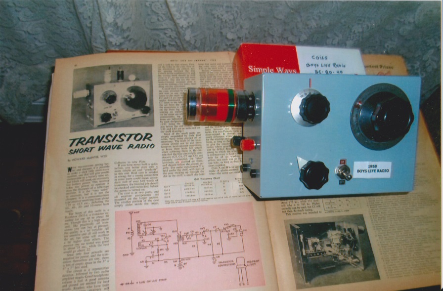
WB3HLHradioWe recently wrote about this three-transistor regenerative receiver from the January 1958 issue of Boys’ Life magazine.

I just received this picture of the completed receiver, constructed by Tom, WB3HLH, of Rockville, Maryland.

As a Cub Scout, he saw the receiver in the magazine and was very interested. This is understandable, since the magazine also carried a feature extoling the virtues of SWL’ing, as well as a listing of the prizes in the annual radio contest.

About 50 years later, he located the magazine and took it upon himself to make one. The article noted that the set was not for beginners, and his experience agrees with this assessment. He notes that the audio stage was simple, but it was very tricky to get the detector oscillating.  As you can see, he very carefully duplicated the layout of the original project.

In addition to the coils described in the article (wound on plug-in coil forms), he wound a coil for the broadcast band. He reports that the set performs well on shortwave, both for broadcast and SSB signals. On the broadcast band, it pulls in all of the major East Coast stations, and signals as far west as KMOX in St. Louis.

The article calls for the use of four penlight batteries, but he reports using a 9 volt battery. The only other circuit modification is the addition of a 3.3 k resistor in parallel with a .01 uF capacitor on the emitter of the detector transistor.


Solar Fire Starter

1980SolarLighterWhen I worked for Radio Shack in an earlier lifetime, one of the more interesting products we sold was the solar cigarette lighter. It was something of a novelty item, but it was also fully functional. It was nothing more than a parabolic mirror, with a little holder at the focal point.  It’s shown above in the 1980 Radio Shack catalog. The idea was to place a cigarette in the holder, point it at the sun, and after several seconds, the cigarette would start smoldering. No, it didn’t work at night or on cloudy days, but on a sunny day, it worked flawlessly.

The same simple device is now available at Amazon.  Taking inflation into consideration, it’s not much more expensive than it was back in the day, and would serve as one method of starting a fire in an emergency. Yes, you’re better off if you have matches or a traditional lighter with you, but redundancy can be a good thing, and it’s kind of fun to amaze your friends by lighting a fire using solar power.

If you don’t smoke (this is one rare case where a cigarette could save your life), then you could use other similar tinder, such as tissue paper, dry grass, or leaves. This device won’t cause anything to burst into flame, so you’ll need more tinder at the ready. As soon as whatever you lit starts to smolder, you’ll need to transfer it to a larger pile of tinder, and then blow on it until it bursts into flame.  You then keep adding larger fuel until you have a fire of the desired size.  You don’t want the fire to go out after it gets dark, because obviously you won’t be able to light another one until morning.

(Some links on this page are affiliate links, meaning that we get a small advertising fee if you purchase from Amazon after clicking on the links.)


Sinking of the Tuscania, 1918

SS Tuscania (1914)

SS Tuscania. Wikipedia Image.

Today marks the 100th anniversary of the sinking of the SS Tuscania, February 5, 1918. The ship was a luxury liner of the Cunard Line, and was serving as a troop transport, carrying American troops to Europe. The ship left Hoboken with 384 crew and 2013 army personnel aboard. On the morning of February 5, a German submarine sighted the convoy and stalked it until darkness. At 6:40 p.m., it fired two torpedoes, one of which sent the ship to the bottom of the Irish Sea. 210 men were killed in the attack.

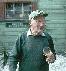
Color picture; An elderly man holding a glass and wearing a hat stands in front of a wooden lodge.

Harry Truman. Wikipedia image.

One of the notable survivors was 20-year-old soldier Harry R. Truman (not to be confused with the President), notable for becoming a victim of Mt. St. Helens in 1980.free-vector-poppy-remembrance-day-clip-art_106032_Poppy_Remembrance_Day_clip_art_small


1968 QRP Rigs

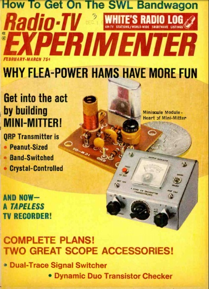
1968JanRadTvExpFifty years ago this month, the January-February 1968 issue of Radio TV Experimenter devoted a considerable number of its pages to Amateur Radio QRP (low power) operation.

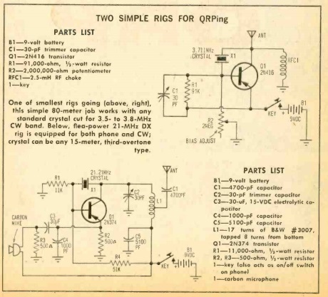
At the time, “QRP” generally referred to power levels of under 100 watts, but the introductory article by Robert M. Brown, K2ZSQ, revealed that many in what was known in ham circles as “that crazy QRP crowd” were seeing what could be done with flea-power setups, often consisting of a single transistor, IC, or tube.  He included these diagrams of minimalist one-transistor QRP transmitters:

1968JanRadTvExpSchematics

The cover feature was the “Mini-Mite,” a QRP transmitter designed by Howard Pyle, W7OE. This was a 4-band transmitter for 80, 40, 20, and 15 meters. The author reported that the set ran an input power of 1.2 watts with a 6 volt power supply, or up to 1.8 watts with a 9 volt supply. His best DX was 1100 miles on 15 meters, 600 miles on 20, 300 miles on 40, and a respectable 200 miles on 80.

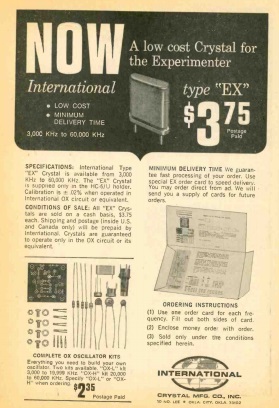
1968JanRadTvExpIntlXtalThe transmitter actually consisted of four transmitters, since it used four of the ubiquitous International Crystal oscillator module kits, and ad for which is shown here from the same magazine. The oscillator cost $2.35, and an additional $3.75 for the necessary crystal. Essentially the oscillators, even though designed for test circuits, were functioning as transmitters, with just a bit of external matching network before the antenna. To switch bands, one transmitter was switched out of the circuit, and one for another band switched in.

It should be noted that it’s likely that none of these 1968 circuits would meet modern spectral purity requirements. Chances are, a bit more external filtering would be required. But the concept shown here is recognizable in many minimalist QRP rigs that are once again in style by “that crazy QRP crowd.”


The Immortal Chaplains: 1943

Stained glass window, Pentagon. Wikipedia image.

  Stained glass window, Pentagon. Wikipedia image.

Today marks the 75th anniversary of the sinking of the troop carrier SS Dorchester, February 3, 1943.

The ship, constructed in 1926, originally carried cargo and passengers between Miami and Boston. She was put into wartime service in 1942 and was converted to a troop carrier. In January 1943, she left New York in convoy bound for Narsarsuak, Greenland. She was torpedoed in the early morning hours of February 3 by a German submarine, which caused severe damage, and the ship sank in about 20 minutes.  672 died, many of hypothermia.

Sinking of the Dorchester. Wikipedia image.

Sinking of the Dorchester. Wikipedia image.

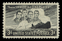
Four relatively new Army chaplains were aboard, First Liuetenants Reverend George L. Fox (Methodist), Reform Rabbi Alexander D. Goode, Roman Catholic priest Father John P. Washington, and Reformed Church in America minister the Reverend Clark V. Poling.  Collectively, they came to be known as the Immortal Chaplains.

As the ship was going down, they helped other soldiers board lifeboats. When the supply of life jackets ran out, they gave up their own. They joined arms, said prayers, and sang hymns as they went down with the ship.220px-Four_Chaplains_stamp1


Happy Groundhog Day!

GroundhogWe always take a break from our scheduled programming for the major holidays, and Groundhog Day is certainly one of the major holidays.

The groundhog shown here appeared a hundred years ago in the May 1918 issue of National Geographic magazine.  As you can see, the groundhog’s shadow is visible, meaning that winter 1918 lasted another six weeks (despite the visible flowers).

The article explains the phenomenon:

The prominence of the groundhog as a popular figure in the country lore of the Eastern States is shown by his having been given a place with the Saints on the calendar, February 2 being widely known as “Groundhog Day.” It is claimed that on this date the groundhog wakes from his long winter sleep and appears at the mouth of his burrow to look about and survey the weather. If the sun shines so that he can see his shadow, bad weather is indicated and he retires to resume his sleep for another six weeks. Otherwise, the winter is broken and mild weather is predicted. Even on the outskirts of Washington some of the countrymen still appraise the character of the coming spring by the weather on “Groundhog Day.”

To help you celebrate with an appropriate holiday dinner, here’s a link to some ground hog recipes.


1950 Soviet “Simplest Shortwave Receiver”

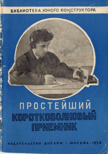
SovietSWReceiverBookCoverWe previously promised that we would be showing you more of this fascinating little book, and here it is!

The book in question is the 1950 Soviet book Простейший коротковолновый приемник (The simplest short-wave receiver) by V.A. Egorov, UA3AB,  part of the series Библиотека юного конструктора (Library of the young designer), a series of small books published between 1937 and 1964 showing various construction projects, many related to radio.
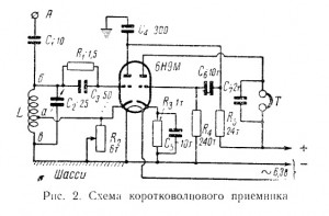
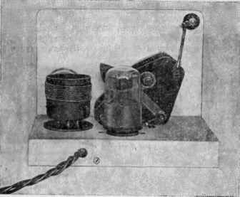
SovietSWReceiverBookSchematicAfter a few pages of introduction to shortwave radio, the book jumps right into a description of the circuit.  As the title of the book promises, the receiver is simple but elegant.  It uses a 6Н9М dual triode (that’s Cyrillic text, so you would read it as 6N9M), one half being used as regenerative detector, with the other half as audio amplifier.  The set employed plug-in coils, and was designed to tune the 40 and 20 meter ham bands.  (For those wishing to duplicate the set with Western parts, the tube appears to be equivalent to a 6SL7.)

The neatly constructed final product is shown below:SovietSWReceiverBook2

SovietSWReceiverBook1

If the book were published in the West, it would probably end there, along with a reminder that you needed to go to your friendly radio dealer or even drug store to buy a B battery for the plate voltage, and an A battery to light the filament.  But in the Soviet Union, it probably wasn’t a sure thing that you could find the battery.  So the book describes four methods to get the power.

The first two methods are power supplies that the reader could build, both of which are more complex than the receiver itself.  Both rely mostly on factory-made parts, but the second set of plans includes instructions for winding the filament transformer at home, with the B+ being rectified directly from the AC line:
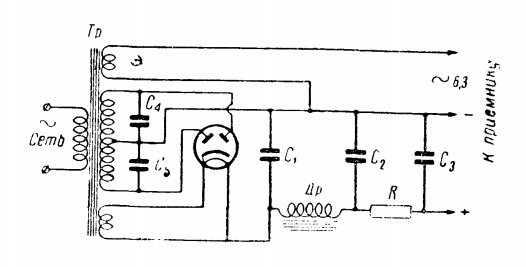
SovietSWReceiverBookPS1

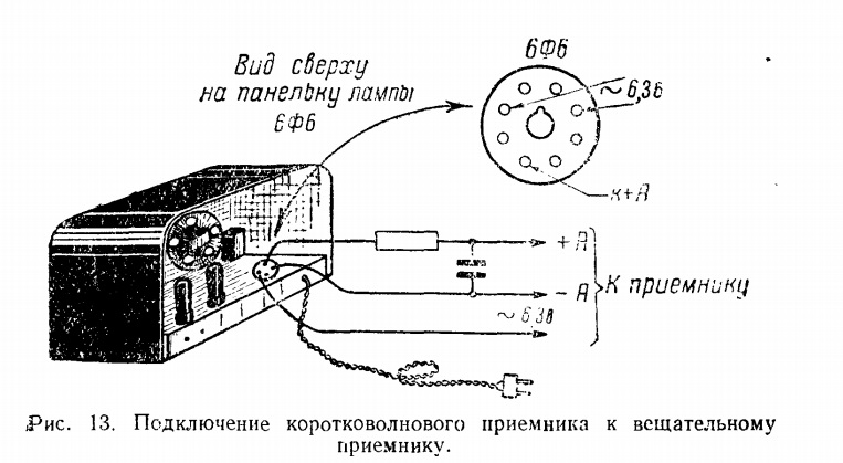
SovietSWReceiverBookPS2But even if the aspiring young Soviet radio fan wound his own transformer, getting the rectifier tube could be problematic.  Therefore, the third method of powering the receiver could be very attractive.  Chances are, the home was already equipped with a broadcast radio, and the broadcast radio had a perfectly good power supply inside.  So the third method involves simply tapping into it by unplugging one of the tubes, and powering the shortwave set right from the socket.  The young SWL just needed to locate the 6Ф6 tube in the family radio, remove the tube, plug his radio into the socket, and his radio would come to life!  Presumably, the other family members would be supportive of the SWL’s new hobby, and forego listening to the broadcast radio as he tuned the short waves.
SovietSWReceiverBookPS3

The fourth method recognizes that some builders might have enough connections so that they can simply go out and buy the battery.  In this case, a БАС-80 battery is required.

After recommending an antenna of 25-30 meters in length, the book jumps into some discussion of how to tune the amateur bands.  It notes, for example, that the 40 meter band can be expected to yield stations about 900-1000 kilometers away, with 20 meters pulling in stations more than 1000 km distant. It explains some of what the listener will hear. For example, in addition to listing some foreign call sign prefixes, it notes that UA call signs are in the RSFSR, UB calls are from Ukraine, and so forth.

It mentions some example SWL call signs, and even shows a reproduction of an SWL card from an SWL in Belarus, with the call sign of UC-2-2002, complete with the familiar address of Box 88 Moscow. Presumably, the text explains exactly how the young listener goes about getting such a call sign and getting his SWL cards printed, but I’m unable to read the text.

SovietSWReceiverBookPSswlcard

The book concludes with a table showing common Q-signals, common CW abbreviations, and the following listing of Soviet and European call sign prefixes.
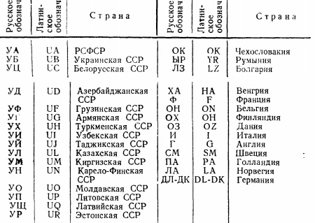
SovietSWReceiverBookPSprefixes

The UA-UR prefixes for the various Soviet republics are listed at the left, with the right column showing the prefixes of Czechoslovakia, Romania, Bulgaria, Hungary, France, Belgium, Finland, Denmark, Italy, Britain, Sweden, Holland, Norway, and Germany.

The SWL card shown above is for reception of UA3AB, and a search for that call sign reveals that it was held by the author of the book, V.A. Egorov.

You can read more about this receiver at this link at the site of VA3ZNW (ex-UA3ZNW, ex-UA3-117-386).  He has a fascinating story of building this set in the 1970’s at the age of 13, and using it to tune in the Voice of America and Radio Liberty.  Even though the Soviets extensively jammed those stations, they didn’t bother jamming them on 16 and 13 meters, since Soviet receivers didn’t tune those bands.  But with the little one-tube homebrew set, they came in loud and clear.