 Prior to World War II, the relatively new FM broadcast band was located at 42-49 MHz. After the war, it moved to its current home at 88-108 MHz. This false start was one of the reasons why FM took years to catch on: The early adopters owned receivers which were now useless, since the stations had all moved.
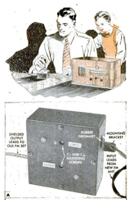
One solution was building a converter, and a number of designs were available. One of the simplest is shown here, and appeared in the April 1947 issue of Popular Mechanics.
The circuit originated with Henry R. Kaiser, the chief engineer of FM station WMOT in Pittsburgh. When WMOT changed frequencies, there were about 6000 obsolete receivers in the area which could no longer hear the station.
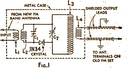
Kaiser originally designed a circuit with a crystal oscillator, and a 1N34 diode as mixer. During experiments, the tube oscillator failed. Much to his surprise, the circuit converted the frequency of another FM station. With a bit of tweaking, he came up with this circuit which put his station on the old receiver’s dial without any power.
The article doesn’t explain how the circuit works, probably because the author didn’t know. But at least for a strong signal, the circuit did work, and could be used to put some of those obsolete sets back in service.
Hi. I have radio tube with am .sw .lw .I want to increase my radio tube with fm frequency. How can I make fm frequency with tube circuit thanks for your help
There’s probably not an easy way to convert it, because the existing radio gets AM signals, and even if you changed the frequency, you wouldn’t be able to hear the FM signals.
The easiest way to do it would be to buy or build a small AM transmitter similar to this one:
Then, just hook that to a modern FM radio, and receive that on the AM band.