From the late 1920’s until the 1960’s, an important tool for air navigation was the Low Frequency Radio Range (LFR).
At its peak, there were about 400 LFR beacons in the United States, and many more worldwide. Each station consisted of a transmitter being fed into two directional antennas. One antenna was sending the Morse letter “A”, dot dash. The other antenna was sending the letter “N”, dash dot. The two signals were synchronized so that the two signals alternated. At four directions from the station, the two signals blended to produce a constant tone. If a plane was off this course in one direction, the pilot would hear the “A” start to get stronger. Off course in the other direction, the “N” would get stronger.
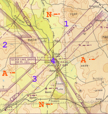
Aeronautical charts such as the one shown here would show the letter that would be heard in each of the four quadrants. Here, in the quadrants south and north of the station, the pilot would hear the letter “N”. In the east and west quadrants, he would hear the letter “A”. On the shaded lines, the pilot would hear the continuous signal. These “beams” would be about a half block wide near the station, and as much as several miles wide far from the station. Most air navigation followed routes along these beams. The course a pilot followed would be along airways connecting the stations, and flying cross country would be a game of “connect the dots” as the pilot flew from one station to the other.
Every thirty seconds, the “A-N” signal would be replaced with the call letters of the station, in this case, RL, which would also be transmitted in Morse.
Despite the simplicity of the system, the accuracy was enough to use for instrument landings, and instrument approaches using the LFR beacons were published for many airports.
For the pilot, only a normal radio receiver was required. In later years, more sophisticated receivers were employed, which would show the pilot visually whether he was on the “A” side or the “N” side of the beam. But in most cases, the pilot navigated by listening to the signal in his headphones.
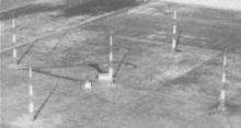
LFR station using Adcock antenna (Wikipedia photo).
Most of the stations operated between 190 and 535 kHz, with powers of up to 1500 watts. Early stations used crossed loop antennas, but Adcock antennas (phased verticals) were used in most later stations.
Directly above the station, there was an inverted “cone of silence” where the directional signal disappeared. Even in times of no visibility, the pilot would know that he had passed over the beacon when the signal disappeared.
Starting in the late 1940’s, the LFR began to be replaced by the VHF Omni Range (VOR). While the VOR required a special receiver in the aircraft, it was superior in that it could be used to “fly a beam” in any direction from the VOR station, rather than just the four possible with the LFR.

Photo courtesy of Ian O’Toole, VK2ZIO, Kurrajong Radio Museum. Used by permission.
Shown here is a BC-1206C Range Receiver, which would have been installed in the aircraft for the purpose of receiving the beacons. This radio, manufactured by Setchell Carlson, Inc., of St. Paul, Minnesota, is a five-tube superheterodyne. As you can see from the schematic, it’s not much different from a standard broadcast receiver.
REFERENCES
- LFR at Wikipedia
- “Flying the Beam” LF/MF Four-Course Radio Ranges by Richard Harris
- Four Course Radio Ranges at AOPA.org
- Blind Flying on the Beam, Journal of Air Transportation, 2003.
- Flying the Radio Beam, page 582, Short Wave Craft magazine, Feb. 1936.
- Flying the Beams, Popular Mechanics, Mar. 1936.
Click Here For Today’s Ripley’s Believe It Or Not Cartoon

Pingback: Minneapolis School A-V Equipment of the 1960′s and 1970′s | OneTubeRadio.com
Pingback: Marine Direction Finding, 1957 | OneTubeRadio.com