Monthly Archives: October 2015

1958 Worm Catcher (Kids: Don’t Try This At Home)

1958WormCatcher

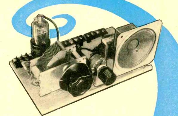
If the project shown in this photo looks dangerous to you, well, that’s probably because it is dangerous.

WARNING:  Do not construct the worm shocker shown on this page!  This is not a construction article.  It is an interesting historical look back at an earlier time when people didn’t worry quite so much about things like electrocution.  

If you ignore my advice, don’t sue me if something goes wrong (and that goes for your heirs, as well).

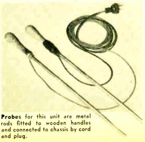
This illustration appears in the 1958 edition of the Electronic Experimenter’s Handbook, published by Popular Electronics.  It is exactly what it appears to be, namely, an AC line cord attached to two metallic probes.  One of the probes has rubber tape near the wooden handle.  The other one has not yet received this gesture toward safety.

Another warning:  If you insist on building this contraption, you must not plug this probe directly into an outlet.  It is plugged into a circuit which provides a small amount of safety.  If plugged directly into household current, it would be positively lethal, instead of just extremely dangerous.  (In fact, if you insist on doing this, it would be a good idea to use a plug rated at 120 volts, but one that does not fit into the normal household outlets, lest someone sees this one part and decides to plug it in to see what it does.)

With all of my earnest warnings out of the way, I’ll disclose what this is. It isn’t a torture device, at least not one for humans.  It’s actually part of a worm catcher, a labor-saving device that will bring earthworms to the surface for easy collection.  It does so by sending household current through the soil.  You stick the probes into the ground, about 3 feet apart, and then plug the probes into the accompanying power supply (and not directly into a wall outlet).  The worms will experience the discomfort of electrical current passing through them, and in an effort to escape, they’ll come to the surface where you can harvest them.

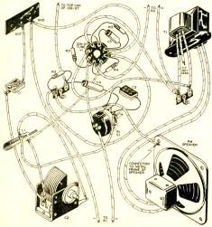
The accompanying article describes two power supplies. The first one consists of little more than two ten-watt light bulbs, one in series with each side of the AC line. The whole circuit is mounted in a wooden box. “Wood was used in this case because of its insulating properties.”

This circuit will undoubtedly trip a modern GFCI outlet. (And by code, any outside outlet should be protected by a GFCI.) Therefore, it probably wouldn’t work today.   I’m not going to explain why it wouldn’t work.  If you don’t know, then you should definitely not build either of these until you’ve brushed up on your electrical theory.

The second circuit is slightly safer, because it includes an isolation transformer. It’s still dangerous, because you’re still playing with 120 volts. It simply eliminates a few of the many possible methods of lethal electrocution. Like the other model, it drops the line voltage somewhat by passing the current through two light bulbs, in this case a 75 watt and a 25 watt in parallel. Since these bulbs probably wouldn’t glow brightly enough to see if the unit is energized, there is a test switch to temporarily remove the 75 watt bulb from the circuit. When the test button is pushed, the 25 watt bulb will provide a visual cue that the probes are correctly in place and the worms are on their way to the surface.

The article does contain a few safety warnings of its own. One of the descriptions starts with the self-evident comment that “the safety factor is the biggest problem involved in the use of house current.” It also warns: “Don’t take any chances by moving the probes when the unit is turned on.”  If the energized probes are safely underground, the effects will presumably be felt only by the worms.  And since the soil is not a perfect conductor, it’s probably not lethal to the worms.  But if the probes are out of the ground while energized, then they pose a hazard to humans in the area.

The editors also add the caution: “Do not attempt to modify either of these circuits. If wired according to the schematics, they will provide [somewhat] adequate protection from the LETHAL 117-volt a.c. household line.”

One warning that’s not mentioned in the article bears repeating.  It notes that if the ground is dry, then watering the ground first could improve performance.  This stands to reason, since damp soil is obviously more conductive than dry soil.  But it also highlights the fact that damp shoes (or bare feet) are better conductors than dry shoes.  So if you insist, despite my warnings, to attempt this method of worm collection, please make sure you’re wearing dry non-conductive shoes.

And remember:  Kids:  Don’t try this at home!


Click Here For Today’s Ripley’s Believe It Or Not Cartoon


1955 Pop ‘Tronics One Tube Receiver

1955PEonetube

Sixty years ago this month, the October 1955 issue of Popular Electronics carried the plans for this one-tube broadcast set.  Even though it had only one tube, it was capable of driving a loudspeaker, thanks to the fact that the tube, a 1D8-GT, was actually three tubes in one.  In consisted of a diode, which was the radio’s detector, a triode, which served as the first AF stage, and a power pentode which drove the speaker.

So even though the set used a single tube, it was the equivalent of a crystal set with two stages of audio.  The article notes that the set gave good performance on strong local stations with just a few feet of wire for an antenna, and that it was able to pull in more distant stations with an outside antenna and ground.

The set was powered by a 1.5 volt A battery and a 90 volt B battery.  The pictorial diagram here1955PEonetubePictorial, more than the schematic, shows the simplicity of the little set.

A piece of wood, 8-1/2 by 5 inches, serves as the base, and the controls and speaker are mounted in place with right-angle brass brackets.  Terminal strips are used for the battery, antenna, and ground connections.


Click Here For Today’s Ripley’s Believe It Or Not Cartoon


Homemade Rectifiers, 1909-1935

Modern bridge rectifier.


Today, if you need a rectifier, it’s a fairly easy matter to buy one. One like the the one shown here will handle 1000 volts and 50 amps, and will only set you back a few dollars. Smaller ones for transistorized circuits can be had for pennies.

In 1935, however, it was a different matter, and parts were not so readily obtainable. Radios would typically use a vacuum tube rectifier, and for other applications such as battery chargers, a “dry” rectifier would commonly be used. In the 1935 Allied Radio Catalog, a “dry” rectifier has a catalog price of $3.73. A full-wave vacuum tube rectifier, the Raytheon BH, has a catalog price of $2.46. These prices don’t sound like a lot, but this was the middle of the Great Depression. And a silver dollar then was worth about the same as a silver dollar today. The only difference is that back then, you had to hand over an actual silver dollar for each dollar on the price tag.

1935 homemade copper oxide rectifier.

1935 homemade copper oxide rectifier.

It’s not surprising, therefore, that someone might decide to make their own. And Popular Mechanics 80 years ago this month, October 1935, showed how. It included circuits for a battery charger, a 6-volt “A” battery eliminator for a radio, and an A.C. voltmeter.

The finished product wasn’t particularly efficient. It required 16 volts AC in order to put out 6 volts DC. A rectifier consists of two dissimilar metals, and in this case, it made use of copper washers, one side of which was oxidized to form copper oxide. The washers were sandwiched between lead washers to form the necessary junction and keep them tightly fixed together.

The copper was oxidized by holding it over a gas flame, either from a bunsen burner or a gas stove. Then, it was left to cool, after which one side was carefully sanded with emery cloth. The pieces were then sandwiched together, with bakeline on the outside layer. The finished product was a bridge rectifier consisting of four diodes.

Building your own rectifiers was nothing new. In the early days of radio, even bigger rectifiers were needed. As I reported in an earlier post, in 1923, T.E. Nikirk, 6KA, solved the problem by building a rotary rectifier. It used a 3600 RPM synchronous motor, meaning that the motor revolved 60 times per second, just like the AC current. Attached was a spinning disk which served to reverse the polarity twice per cycle. In comparison, the 1935 “dry” rectifier seems tame.  Interestingly, the silicon rectifier at the top of the page probably has about the same ratings as 6KA’s massive spinning contraption.

1909 Chemical Rectifier.

1909 Chemical Rectifier.

More common in the early days of radio was the “wet” chemical rectifier, such as the one shown here from a 1909 issue of Popular Electricity.
It consisted of diodes made out of glass jars, each containing lead and aluminum electrodes, in a solution of ammonium phosphate.  A similar rectifier for use in a CW transmitter is described in a February 1921 QST article by P.J. Furlong, 1FF. For the electrolyte in his eight jelly jars, he used Twenty Mule Team Borax.

The modern silicon rectifier seems like a trivial component, and I don’t suppose I would try to save a few pennies by making my own.  But it comes under the category of things that it’s nice to know are possible.  You can make your own rectifier, and these old pioneers of electricity and radio showed that it was possible.

Click Here For Today’s Ripley’s Believe It Or Not Cartoon