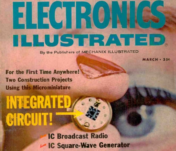
Fifty years ago this month, the cover of the March 1965 issue of Electronics Illustrated showed this integrated circuit, the Motorola MC556G. The case of this IC measured 5/16 inch in diameter, and the chip itself measured about 1/10 inch square. It contained six transistors and eight resistors. The accompanying article noted that it was now on the market at a price that hobbyists could afford to use for experimental projects, $3.35.
To put the new device in perspective, the article compared it to the still ubiquitous 5-tube radio, which consisted of about six basic circuits using about 20-30 components. The article noted that the day would soon arrive when one or two IC’s would constitute a “complete radio that is equivalent in performance to that five-tube AC/DC job.” That prediction came true only seven years later, in 1972 with the ZN414 AM radio IC from GEC-Plessey. The modern functional equivalent of that IC is the MK484/TA7642 am-Radio IC, which is a complete radio in a chip, requiring as its only external components a battery, coil, tuning capacitor, and earphone.
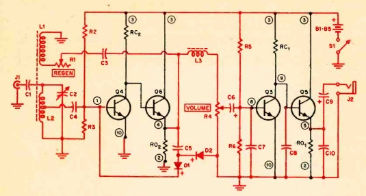
While the eight transistors in a 1/10 inch package was revolutionary at the time, transistors in current IC’s are in the range of tens of nanometers in size, allowing several billion transistors per chip. But building something with an IC was revolutionary fifty years ago, and Electronics Illustrated featured two projects making use of the MC356G. The first was a square-wave signal generator, and the second was the AM radio shown below. In this diagram, the portion shown in black is internal to the IC, and the components shown in red are external. As you can see, the circuit makes use of four of the chip’s eight transistors, and four of its resistors.
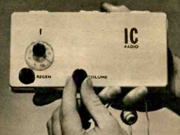
The IC was designed for use as a logic gate, but transistors are transistors, and they could be used for their amplification function. For the radio in particular, getting the circuit to work took several experimental designs, but the author finally “hit upon one that has a decent amount of sensitivity, selectivity, and audio output.” The author noted that most of the headaches in designing the radio were caused by the close proximity of the components on the chip. Having only 1/10 of an inch to work with presented leakage paths between the circuits that would be out of the ordinary for a radio designer. The finished project is shown here.
In the design, two of the transistors are used as RF amplifiers, with the signal being fed back through a regeneration control. The second of those transistors also amplifies the audio, and there are two more audio amplifier stages. The actual detector consists of two external diodes.
Click Here For Today’s Ripley’s Believe It Or Not Cartoon
![]()


