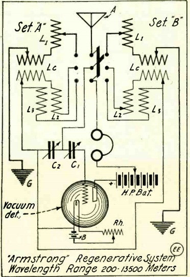
Earlier this year, we posted a diagram of a regenerative receiver from January 1916, which was probably the first construction article detailing such a receiver. The December 1916 issue of the same magazine, Electrical Experimenter, contains this diagram of an unusual regenerative set.
This is basically two receivers, with the most expensive parts, the audion tube and variable capacitors, shared between them. Different coil arrangements could be switched into the circuit with a three pole double throw knife switch. With the switch set to the “Set A” circuit, it was a standard audion detector. With the switch flipped to the “Set B” circuit, it became a regenerative detector. Regeneration was controlled by the coupling between L2 and L1. In position A, the set could be used to receive damped waves from a spark transmitter. With it set to position B, it could be used for undamped continuous waves, and “a pure musical note may be obtained of any frequency, in the telephones.”
The accompanying article, by Samuel Curtis, Jr., first pointed out that the set could be constructed without the switch. But the circuit was designed this way because the parts were expensive.
The article noted that “the Audion bulb need not necessarily be of the most costly type, but can be any one of the tubular Audions. These bulbs give exceptional satisfaction in connection with this system, and if the experimenter should happen to be an owner of a frozen bulb, or one that will not oscillate properly, he will find that in most cases it will oscillate with this system.”
According to this site, the 1916 price of a tubular Audion was $11. As a point of comparison when looking at old prices, it’s good to remember that the cost would be 11 silver dollars, or about 11 ounces of silver. At today’s prices, this would translate to about $176. So the concept of economizing and building two receivers instead of one with the same tube doesn’t seem surprising.