Monthly Archives: January 2017

Answer to Yesterday’s Quiz

1956DecQuistQuizA

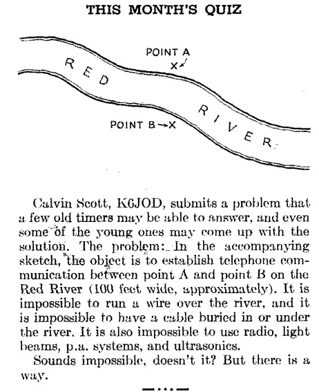
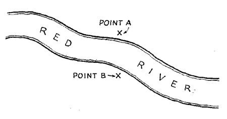
Yesterday, we presented the problem of how to hook up a telephone to talk across a river from Point A to Point B, without running a wire across the river.

Loyal readers knew the answer right away, because we presented a similar system for a 1940 wireless telegraph using four ground rods.  Each side of the circuit was connected to two ground rods.  The January 1957 issue of QST shows a similar arrangement for how the two Boy Scouts could hook up their field telephone:

1957JanQuistQuiz2

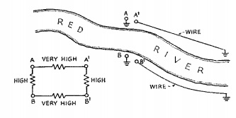
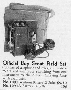
Each telephone is hooked up to two ground rods.  The magazine suggests separating them by 20 times the width of the river (2000 feet).  There’s still a high resistance path between the two telephones, but the leakage resistance between A and A’ and between B and B’ is even higher.  The 1940 wireless telegraph, because it used an audio amplifier, could probably get by with less separation between the ground rods on each side of the river.  But with 2000 feet separation, the scouts’ telephones should work just fine, despite not being able to run any wire across the river.


Boy Scout Field Telephone-Telegraph, 1937

1937JanBLEighty years ago this month, the January 1937 issue of Boys’ Life carried this ad for the official BSA field set, a field telephone and telegraph.  For $9.50, a scout could acquire two such units.  The possibilities for use during hiking and camping, or between two friends’ houses, seem limitless.

More details are given in an ad appearing in the February 1934 issue, which reveals that the set is manufactured by the American Electric Company, of 1033 West Van Buren Street, Chicago, “one of the world’s foremost makers of commercial telephone equipment.”  Contained in a durable khaki colored weatherproof case having a strong carrying strap, the set was ready for use at any time by simply connecting to line wires.  The set was said to have a range to be able to signal and talk clearly over a thousand feet.  The set was switched from telephone to telegraph simply by switching the key into the telegraph position.

The set was patented under US Patent 2072264, which described the set as being “inexpensively and ruggedly built to fill the need for such an assembly by Boy Scout organizations and others having need for inexpensive equipment which may be employed to establish temporary or permanent telephone-telegraph communication between two points.”

The only evidence of a surviving example I was able to find online was this eBay listing, which unfortunately contains only a photo of the unit in the closed position.

A resourceful Boy Scout owning such a telephone probably wouldn’t have had much trouble figuring out the Quist Quiz which appeared in the December 1956 issue of QST:

1956DecQuistQuiz

Two Scouts, one on each side of the river, are equipped with their official BSA field telephone-telegraph sets.  Without crossing the river or running a wire across the river, how can they hook up the phones?

Loyal readers of OneTubeRadio.com already know the answer, since we previously showed a similar system.  If you missed it, you’ll need to wait until tomorrow to see the answer.


Zimmermann Telegram, 1917

Zimmermann Telegram, as sent from Washington to Mexico City. Wikipedia image.

Today marks the 100th anniversary of the Zimmermann Telegram, which played a key role in the entry of the United States into the First World War.  The message was originally sent from Germany on January 11, and on January 19, 1917, it made the final leg of its circuitous route to Mexico City.

Interestingly, the telegram was routed through Britain, which allowed the British to intercept and decode it.  Because the Germans had no wire communications with America, President Wilson allowed them to send diplomatic cables courtesy of the American embassy in Copenhagen.  That was routed through Britain, where the British were able to intercept it.

From the German embassy in Washington, the cable was sent to Mexico City by Western Union.  The telegram instructed the German ambassador to Mexico to propose, if hostilities appeared imminent, an alliance between Germany and Mexico.


Sourcing Radio Parts in 1927

1927JanRadioNews

Radio hobbyists have long been aware that many common household objects have their highest and best use as radio components. So when this gentleman, shown on the cover of Radio News, January 1927, needed an enclosure as part of the radio he was working on, it was only natural to put the bread box to better use than it had previously seen.

Unfortunately, it appears that his wife didn’t have the same priorities, since she had to find another container for the bread.

Answer to Yesterday’s Quist Quiz

Yesterday, we offered this schematic from 1957, and asked for the effective resistance between points A and B:

1957JanQuistQuiz

The answer is 1 ohm.  If you look closely at the diagram, despite the confusing layout, the three resistors are in parallel.  Point A is connected to the left side of two of the resistors, and Point B is connected to the right side of two resistors.  The only complicating factor is that the middle resistor is backwards:  A is connected to the right side, and B is connected to the left side.  Since the polarity doesn’t matter, it’s just three resistors in parallel.  So the equivalent resistance is 1 / ((1/3) + (1/3) + (1/3)) = 1 ohm.


Quist Quiz, Jan. 1957

This little quiz appeared in QST sixty years ago, January 1957. The answer will appear tomorrow. If you can’t wait, the answer appeared in the magazine’s February 1957 issue.

1957JanQuistQuiz


1977 Pong-IV Kit

1977Pong

Forty years ago this month, this couple is enjoying a friendly game of Pong, as shown on the cover of the January-February 1977 issue of Elementary Electronics.

As detailed in the accompanying article, they put the game together themselves, thanks to the Interfab Pong-IV video game kit. The unit contained 43 integrated circuits, and came in three forms. For the purist kit builders, the set came with all of the parts, and the builder had to populate the circuit board and solder them. To save a considerable amount of labor, it was also available with the board pre-populated with parts, held in place by a plastic blister pack. The builder then merely had to solder the multitude of small connections and then remove the plastic. Finally, it was available in semi-kit form, with the circuit board already soldered, and only minimal mechanical assembly required.

The kit was originally marketed with a built-in UHF transmitter to hook directly to the TV. However, the FCC cracked down and required type acceptance, which wasn’t economically viable. Therefore, the PC board was all ready to go, and the manufacturer provided a parts list and instructions to install the transmitter, using a 2N5770 transistor and a few other parts. Other options were to separately purchase a UHF transmitter, for a cost of about $8.50, or tap right into the TV’s video amplifier (this was before the days of most TV’s having a video input jack).

The kit was offered by the Interfab Corp., of Laguna Niguel, California. The completed kit sold for $89.50, with the less assembled versions being about $10 less.


1917 Miniature Receiver

1917janpm2A century ago, the January 1917 issue of Popular Mechanics showed this surreptitious radio receiver having the size and appearance of a fountain pen. It was said to “make it possible for a man in the streets to pick up messages sent out from any station in the immediate vicinity.”

A tiny speaker was mounted at one end, behind which three small batteries provided power. The miniature audio tube was mounted at the other end, with coil and condenser behind it. Tuning was effected my moving a ring encircling the coil. Tiny connectors on each side were provided for antenna and ground. The antenna could consist of a wire running down a sleeve to a cane, and the ground was a wire running down the trouser to a metal plate in the heel of one shoe. To listen, the user could hold the cane at arm’s length into the air and put his heel against a fire plug or other metal object. By holding the tiny speaker into his ear, he could pick up messages without difficulty.


Boy Scouts Distribute Air Raid Posters: 1942


1942jan12chitrib
In hindsight, the likelihood of air raids against Chicago during the Second World War seems small. But the Windy City, as well as the entire region, was a bit safer thanks to the efforts of the Boy Scouts, as reported by the Chicago Tribune75 years ago today, January 12, 1942. According to this article, the 110,000 Boy Scouts in Illinois, Wisconsin, and Michigan were making plans to distribute air raid instruction posters throughout the region.

According to the article, Chief Scout Executive James E. West had wired civil defense officials that the Scouts “would keep on the job until the nation is blanketed with air raid posters and all communities can join the Boy Scouts in being prepared for the emergencies that war may bring us.”

For more information about Boy Scouts during World War II, see my earlier post.


Wabash Blackout Lamp, 1942

1941janservice

Shown here from 75 years ago is a blackout light bulb, manufactured by the Wabash Appliance Corp., 335 Carroll St., Brooklyn, NY. The bulb provided a beam of blue light that was projected downward, for use indoors during wartime blackouts. The inside of the 25 watt bulb had a silver reflector to hide filament glare and direct the beam downward.

It is shown here mounted in a socket, from the January 1942 issue of Service magazine.


1917 Boys’ Life Transmitter

1917janblA hundred years ago this month, the January 1917 issue of Boys’ Life magazine carried the plans for constructing this wireless sending set. The author, A. Frederick Collins, had written the previous month on how to construct a receiver.

He notes that five parts are required: A spark coil, a tuning coil, a telegraph key, a spark gap, a battery, and an aerial switch, hooked up as shown here. The spark coil, the same type used for gas engine firing, was available for about five dollars. For those who wished to build their own, he directed readers to his own Book of Wireless, which contained more complete plans.

The tuing coil could also be procured for about five dollars, but he notes that a boy could easily make his own, and provides details.

He concludes:

A wireless telegraph set will give you all the apparatus you need for you to experiment with and theory to rack your brains over and on for the rest of your life, and it will also give you a liberal education in a highly specialized field of electricity.