Monthly Archives: May 2016

1956 Pop Up Antenna Tower

1956PopUpTower

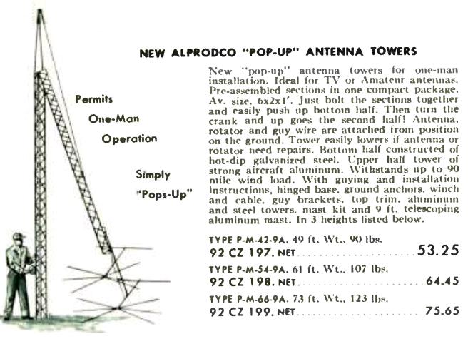
This is either a great idea, or a really bad idea. Whichever it was, it appeared in the 1956 Allied Radio catalog.  The idea was simplicity itself, as revealed by the diagram. One man can put up an antenna and a 73 foot tower without ever leaving the ground. “Just bolt the sections together and easily push up bottom half. Then turn the crank and up goes the second half!” The bottom half was steel, and the top half was aluminum. What could possibly go wrong?

Sixty years later, these don’t seem to be available, and even though I’m not a mechanical engineer, I think I can see a couple of reasons why. First of all, I bet the top section needs a little nudge from a second man on the ground to start cranking from that insanely acute angle, but that’s not an insurmountable problem. I would definitely want to be wearing a hardhat when the top section travels the last couple of inches, since it seems to me that it’s going to drop into place by gravity without any control from the crank. And during the time that the top half is sticking out perpendicular, I would think that it really needs to be firmly tied down on the other side, to keep the whole thing from tipping over.

The biggest problem I see is that the cable is a permanent structural part of the tower. If the cable breaks, or even if some curious passerby wonders what happens when the crank is turned, nothing is holding up the tower other than gravity and the guy wires.

The description says that it will withstand 90 MPH winds. But I wouldn’t want to be standing anywhere near it when those winds were blowing.

Of course, maybe I’m wrong about those things. If so, then this is a great idea.

Click Here For Today’s Ripley’s Believe It Or Not Cartoon


Babette Goes To War: 1959

BabbetteGoesToWar

Shown here under the sheets is Brigitte Bardot from the 1959 French comedy Babette Goes to War (Babette s’en va-t-en guerre). Of particular interest to our readers is, of course, what she’s doing under the sheets, namely, sending CW.  Babette, a French country girl in London, played by Mlle. Bardot, does her part in the war effort by parachuting into German-occupied France to kidnap a German general. She bumbles through her mission with a heroic finish.

In this still from the movie, the naysayer might point out that her technique with the key leaves something to be desired. However, the criticism is unwarranted given the circumstances. She is transmitting from underneath her sheets in the very hotel that was serving as the Nazi headquarters. The German direction-finding truck pinpoints her location, a Nazi bursts into her room, only to retreat when the girl under the sheets protests that she’s naked.

The film was a big hit in France, with over 4.6 million tickets sold. On this side of the Atlantic, the New York Times review proclaimed the film to have “the anomalous distinction of being occasionally farcical and somewhat incomprehensible.” The review lamented that “Bardot is clothed almost as abundantly as an Eskimo most of the way through this World War II spoof, and a fully dressed Mlle. Bardot is downright confusing.”

The movie’s trailer, which includes the exciting scene of Mlle. Bardot being tracked by the Nazi DF’ers, in shown here:

This clip shows her send and receive the complete message;

She sends mostly V’s, and a few other random characters which, according to the CW to French subtitles, mean “ALLO LONDRES – LE LEOPARD EST DAN LA CAGE AUX MOUCHES – STOP – C’EST DU PEU AU JUS – FAITES CHAUFFER LA COLLE.” She gets the message back from London, which sounds like “OK OK” to me, but according to the subtitles means “COMPRIS – TRES BIEN – MESSAGE TERMINE.”

The movie doesn’t appear to be available in North America, but you can get a PAL version at Amazon.

Click Here For Today’s Ripley’s Believe It Or Not Cartoon


ARRL Trunk Lines, 1916

1916ARRLtrunklines

This map appeared a hundred years ago, in the February, 1916, issue of QST. It accompanied an article by Hiram Percy Maxim, 1AW, calling for the establishment of regular “trunk lines” across the United States. He envisioned “a citizen of Portland, Maine, being able to send a message to a citizen in Portland Oregon, by wireless, and without cost” on a reliable basis. As the Washington’s Birthday test illustrated, it was possible for hams to send traffic to every point in the nation extremely rapidly. But what was lacking was the ability to do so on a routine basis.

Maxim envisioned having operators along these trunk lines standing by at a scheduled time on a daily basis to make this kind of traffic routine. At the time, wireless communication by amateurs was limited to a few hundred miles. Therefore, to get messages from one end of the country to the other, these trunk lines would ensure that stations within range would be available at a predictable time.

For example, “Trunk Line A” along the country’s northern tier would include stations in or near the following cities: Portland, ME; Boston, MA; Albany, NY; Buffalo, NY; Cleveland, OH; Toledo, OH; Detroit, MI; Chicago, IL; Minneapolis, MN; Fargo, ND; Helena, MT; Spokane, WA, and Seattle, WA. Each hop was within the capabilities of a well-equipped station of the time, and a message could cross the country in only 12 steps.

This concept was ultimately adopted, and ultimately became a part of the ARRL National Traffic System.

Click Here For Today’s Ripley’s Believe It Or Not Cartoon


Memorial Day Sesquicentennial

free-vector-poppy-remembrance-day-clip-art_106032_Poppy_Remembrance_Day_clip_art_smallWhile there are competing claims for the exact date and place, today marks the 150th anniversary of the first (or certainly one of the first) official observances of Memorial Day.

On May 5, 1866, a ceremony was held in Waterloo, N.Y., to honor local veterans of the Civil War. Flags flew at half staff, and local businesses closed in observance. In 1966, the U.S. Congress declared this to be the “birthplace” of Memorial Day.

It was first recognized as a federal holiday in 1971, when it was placed on the last Monday in May.

References

Memorial Day History at U.S. Department of Veterans Affairs

Click Here For Today’s Ripley’s Believe It Or Not Cartoon


1956 Popular Electronics 4 Transistor Receiver

1956MayPE


Sixty years ago this month, the May 1956 issue of Popular Electronics carried the plans for this four-transistor portable radio “with a punch.”  It promised loudspeaker volume at home or at the beach, all without an external antenna.

As revealed by the schematic below, the radio was basically a crystal set, with the four transistors serving as an audio amplifier.  Sixty years ago, the germanium transistors (CK721 and CK722) available for hobbyists weren’t quite ready for prime time when it came to RF.  The crystal set was designed to work without an external antenna by using a ferrite-core coil as the antenna, with the tuning capacitor in parallel with the entire coil.  But to match the impedance of the diode detector and maintain a high Q factor, the coil was tapped at one end for connection to the diode.  The article promised that loudspeaker volume on local stations could be achieved with this setup.

1956MayPESchematic
Click Here For Today’s Ripley’s Believe It Or Not Cartoon


1966 Boys’ Life Signaler

1966MayBL

This simple Morse Code practice device dates back fifty years, to the May 1966 issue of Boys’ Life.  At the time, Scouts had to know both semaphore and Morse Code to earn the First Class rank, and this set let them practice sending and receiving Morse Code via the “wigwag” method, using a flag.

According to the magazine, the idea was sent in by Scouts from Troop 240 of Fair Lawn, N.J. It was simplicity itself–it was just a block of wood, with a small version of the flag mounted on a coat-hanger wire. The code was printed on top of the block, and “even a Tenderfoot can send messages–since he can read code from board–and he’ll unconsciously start learning the code early.”

The bill of materials called for a piece of red felt, a white patch for the middle, a coat hanger, some tape, a pine block, and “one ambitious Scout.”

Click Here For Today’s Ripley’s Believe It Or Not Cartoon


Resistor Color Codes, 1941

1941MayPMColorCodes

It turns out that the resistor color code dates back about 75 years, to 1941. Here, in the May 1941 issue of Popular Mechanics, it appears for the first time. According to the magazine, the color coding method was developed by the Radio Manufacturers Association (RMA) and was in common use. The magazine lists two methods for using the color code, the first of which, using four colored bands, is still in common use. Another method for irregularly shaped resistors, was to use the body color for the first digit, a band on one end for the second digit, a narrower band or dot for the multiplier, and a thinner band on the other end for the tolerance.

The familiar color code of Black, Brown, Red, Orange, Yellow, Green, Blue, Violet, Gray, and White is given in the chart. Over the years, this has given rise to a number of mneumonic devices for remembering the order in the form of a memorable sentence using the same first letters. Many of these are what Wikipedia puts in the “offensive” category, with many of them involving something untoward happening to some poor girl named Violet.

I first learned the resistor color code from the Boy Scout Radio Merit Badge pamphlet, meaning that I still have occasion to recite the less salty phrase, “Better Be Right Or Your Great Big Venture Goes West,” while counting off the digits on my fingers.

Click Here For Today’s Ripley’s Believe It Or Not Cartoon


1954 High Gain Low Drain Portable

RadioElectronics1954March

The plans for this “high gain, low drain portable radio” appeared in the March 1954 issue of Radio Electronics magazine.  It appears to be a good performer, but it was designed both for performance and low battery drain, and the author explained why:

When anybody anybody mentions “portable radio,” most of us think immediately of the entertainment it can provide.  The Set can go with us on picnics, vacation trips, and boat rides. We can enjoy ball games, national events and all our favorite programs while we work, play, and travel. But there is a serious side to this matter. In these days of H-bombs and supersonic jets, a portable radio might mean the difference between life and death. If that terrible day should ever come when air-raid sirens wail for real, the Conelrad system will go into effect. If worst comes to worst, if power goes out and wires down, civil defense messages and other essential communications will continue. In such an emergency, a portable radio can become a very important item.

With that in mind, the key design factor was low battery drain. A few years later, transistors would make that goal easy. But the current transistors on the market, while suitable for low-powered audio, weren’t yet ready for use with RF. Therefore, the design of this set was a hybrid–it contained two tubes, a 1E8 serving as oscillator and mixer, with a 1AD5 serving as IF amplifier. Then, solid state took over, with a 1N34 diode as the detector, and two CK722 transistors providing enough audio amplification to drive a speaker. For more distant stations, a headphone jack was provided.

Because of the hybrid design, the set required three batteries, but they were all set up to minimize current draw. The transistors were powered by 4.5 volts, provided by three dry cells. The filaments were powered by another 1.5 volt dry cell, but the author noted that these could be run on a battery so low that it was no longer useful for a flashlight. In addition, there was a potentiometer in series with the filaments. This would serve, to a certain extent, as a volume control. But more importantly, it would allow the filament current to be set to the lowest possible position.

The B+ for the tubes was provided by a 45 volt battery. Here, another battery saving trick was employed. The set contained a switch for local/long-distance. For strong local stations, a 56k resistor was switched in series with the B battery. This reduced the B+ current to only 50 microamps, just barely enough to keep the RF section running. For more distant stations, this resistor was bypassed, and the tubes ran on the full 45 volts, drawing about 1.6 mA.

The author reported that the set worked well with local stations, even in a skyscraper, or even in a subway or tunnel. He reported pulling in stations as far as 500 miles away with the telescoping antenna, normally designed for use as an automobile antenna.

RadioElectronics1954MarchSchematic

Click Here For Today’s Ripley’s Believe It Or Not Cartoon