The plans for this “high gain, low drain portable radio” appeared in the March 1954 issue of Radio Electronics magazine. It appears to be a good performer, but it was designed both for performance and low battery drain, and the author explained why:
When anybody anybody mentions “portable radio,” most of us think immediately of the entertainment it can provide. The Set can go with us on picnics, vacation trips, and boat rides. We can enjoy ball games, national events and all our favorite programs while we work, play, and travel. But there is a serious side to this matter. In these days of H-bombs and supersonic jets, a portable radio might mean the difference between life and death. If that terrible day should ever come when air-raid sirens wail for real, the Conelrad system will go into effect. If worst comes to worst, if power goes out and wires down, civil defense messages and other essential communications will continue. In such an emergency, a portable radio can become a very important item.
With that in mind, the key design factor was low battery drain. A few years later, transistors would make that goal easy. But the current transistors on the market, while suitable for low-powered audio, weren’t yet ready for use with RF. Therefore, the design of this set was a hybrid–it contained two tubes, a 1E8 serving as oscillator and mixer, with a 1AD5 serving as IF amplifier. Then, solid state took over, with a 1N34 diode as the detector, and two CK722 transistors providing enough audio amplification to drive a speaker. For more distant stations, a headphone jack was provided.
Because of the hybrid design, the set required three batteries, but they were all set up to minimize current draw. The transistors were powered by 4.5 volts, provided by three dry cells. The filaments were powered by another 1.5 volt dry cell, but the author noted that these could be run on a battery so low that it was no longer useful for a flashlight. In addition, there was a potentiometer in series with the filaments. This would serve, to a certain extent, as a volume control. But more importantly, it would allow the filament current to be set to the lowest possible position.
The B+ for the tubes was provided by a 45 volt battery. Here, another battery saving trick was employed. The set contained a switch for local/long-distance. For strong local stations, a 56k resistor was switched in series with the B battery. This reduced the B+ current to only 50 microamps, just barely enough to keep the RF section running. For more distant stations, this resistor was bypassed, and the tubes ran on the full 45 volts, drawing about 1.6 mA.
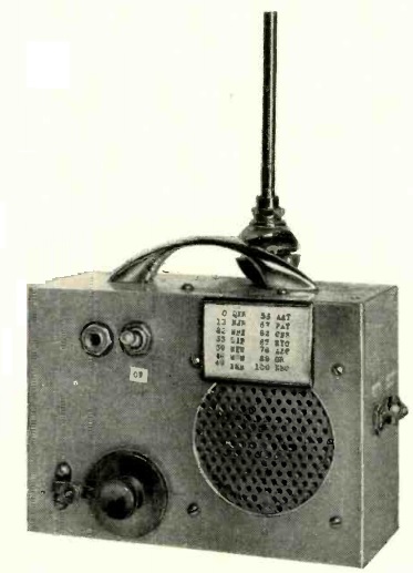
The author reported that the set worked well with local stations, even in a skyscraper, or even in a subway or tunnel. He reported pulling in stations as far as 500 miles away with the telescoping antenna, normally designed for use as an automobile antenna.

Click Here For Today’s Ripley’s Believe It Or Not Cartoon
