
Modern bridge rectifier.
Today, if you need a rectifier, it’s a fairly easy matter to buy one. One like the the one shown here will handle 1000 volts and 50 amps, and will only set you back a few dollars. Smaller ones for transistorized circuits can be had for pennies.
In 1935, however, it was a different matter, and parts were not so readily obtainable. Radios would typically use a vacuum tube rectifier, and for other applications such as battery chargers, a “dry” rectifier would commonly be used. In the 1935 Allied Radio Catalog, a “dry” rectifier has a catalog price of $3.73. A full-wave vacuum tube rectifier, the Raytheon BH, has a catalog price of $2.46. These prices don’t sound like a lot, but this was the middle of the Great Depression. And a silver dollar then was worth about the same as a silver dollar today. The only difference is that back then, you had to hand over an actual silver dollar for each dollar on the price tag.
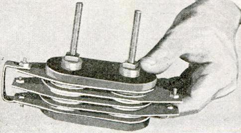
1935 homemade copper oxide rectifier.
It’s not surprising, therefore, that someone might decide to make their own. And Popular Mechanics 80 years ago this month, October 1935, showed how. It included circuits for a battery charger, a 6-volt “A” battery eliminator for a radio, and an A.C. voltmeter.
The finished product wasn’t particularly efficient. It required 16 volts AC in order to put out 6 volts DC. A rectifier consists of two dissimilar metals, and in this case, it made use of copper washers, one side of which was oxidized to form copper oxide. The washers were sandwiched between lead washers to form the necessary junction and keep them tightly fixed together.
The copper was oxidized by holding it over a gas flame, either from a bunsen burner or a gas stove. Then, it was left to cool, after which one side was carefully sanded with emery cloth. The pieces were then sandwiched together, with bakeline on the outside layer. The finished product was a bridge rectifier consisting of four diodes.
Building your own rectifiers was nothing new. In the early days of radio, even bigger rectifiers were needed. As I reported in an earlier post, in 1923, T.E. Nikirk, 6KA, solved the problem by building a rotary rectifier. It used a 3600 RPM synchronous motor, meaning that the motor revolved 60 times per second, just like the AC current. Attached was a spinning disk which served to reverse the polarity twice per cycle. In comparison, the 1935 “dry” rectifier seems tame. Interestingly, the silicon rectifier at the top of the page probably has about the same ratings as 6KA’s massive spinning contraption.
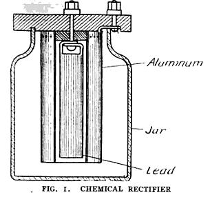
1909 Chemical Rectifier.
More common in the early days of radio was the “wet” chemical rectifier, such as the one shown here from a 1909 issue of Popular Electricity.
It consisted of diodes made out of glass jars, each containing lead and aluminum electrodes, in a solution of ammonium phosphate. A similar rectifier for use in a CW transmitter is described in a February 1921 QST article by P.J. Furlong, 1FF. For the electrolyte in his eight jelly jars, he used Twenty Mule Team Borax.
The modern silicon rectifier seems like a trivial component, and I don’t suppose I would try to save a few pennies by making my own. But it comes under the category of things that it’s nice to know are possible. You can make your own rectifier, and these old pioneers of electricity and radio showed that it was possible.
Click Here For Today’s Ripley’s Believe It Or Not Cartoon
